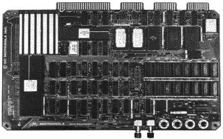

Introduced around 1982, the MC68000 Educational Computer Board provides a complete microprocessor system on a single small printed circuit board, including a 4MHz MC68000 16-bit microprocessor, 32KB of memory, 16KB of firmware, parallel input/output (I/O), and serial communications I/O. The user must only connect an RS-232C compatible dumb terminal and power supplies to have a functional system. The firmware, aptly named "TUTOR", provides the user with monitor/debug, assembly/disassembly, program entry, and I/O control functions.
Position the MECB so the CPU is on the lower left, the power connectors are on the lower right, and the card edge connectors are on the top (just like in the picture above). The card edge connectors are, from left to right, the parallel printer port (requires a custom cable), the audio cassette port, the terminal serial port, and the host (modem) serial port.
I never use the printer port, the cassette port, or the host port. The terminal port is the port that gets connected to the PC serial port. I attached a ribbon cable to the terminal port (pin 1 is on the left) with an edge connector on one end and two DB25 connectors (1 male, 1 female) on the other end. To connect the board to the PC, run a DB25 straight-through cable from the terminal port to the PC serial port.
On the right side of the board, between the RAM and ROM, there are two sets of jumper pins. The top set selects the terminal port baud rate; the bottom one selects the host port baud rate. I set them both to 9600 baud (the fastest setting available) by shorting only the leftmost pair of pins in each set of jumper pins. Unless someone has modified the circuit board, both the send and receive rate should be identical.
Set your PC terminal program to 9600,E,7,1.
Next to the power connectors are the red abort switch and the black reset switch. After connecting your PC to the MECB, press the reset switch. You should see a prompt similar to
TUTOR 1.3 >