| 100 | 106 | CF 188 | CF 208 | CFCP 290 | CFCP 293 | CFCP 295 | CFCP 296 | CFCP 297 | 401 | 402 | |||||||||||||||||||||||||||||||||||||
|---|---|---|---|---|---|---|---|---|---|---|---|---|---|---|---|---|---|---|---|---|---|---|---|---|---|---|---|---|---|---|---|---|---|---|---|---|---|---|---|---|---|---|---|---|---|---|---|
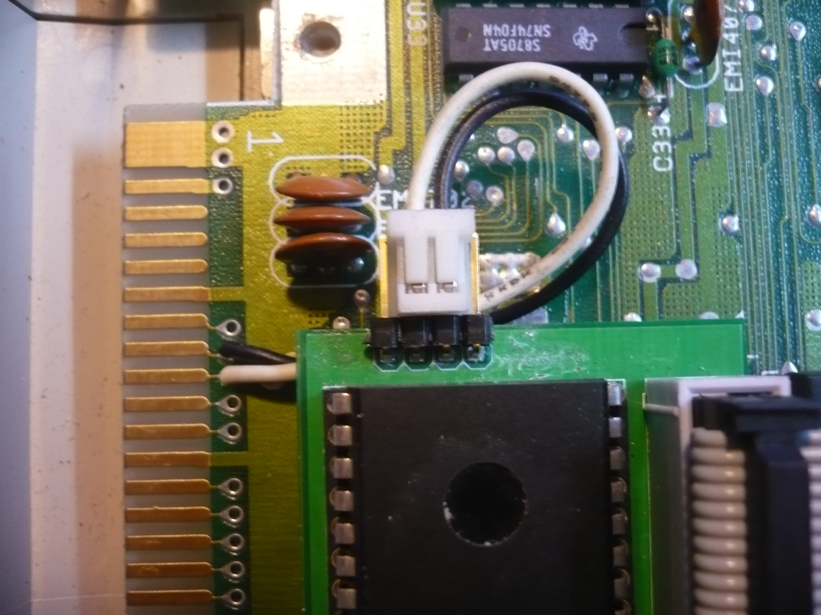
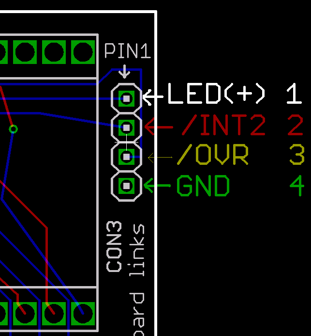
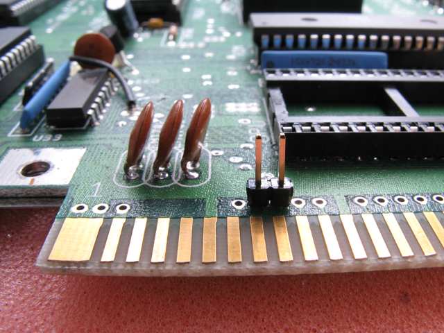
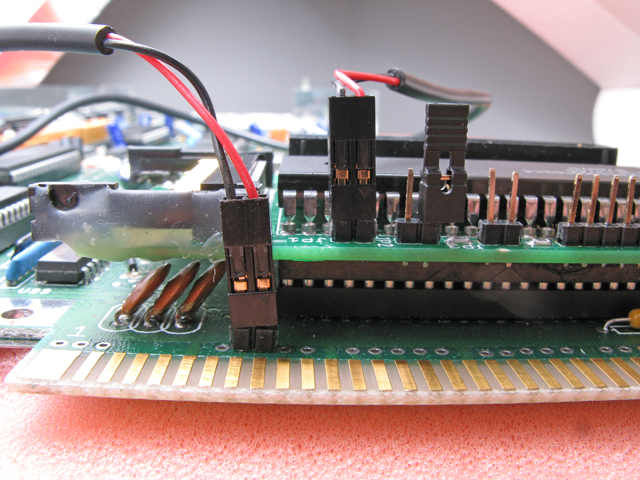
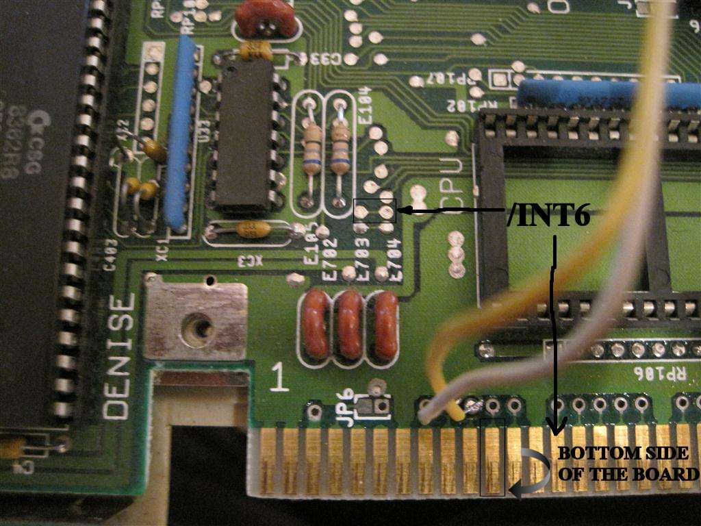
| /int2, /ovr | JPG (src)
, | JPG 1, | A2K JPG1, 2
|
V6a-A500 | below img
| ascii
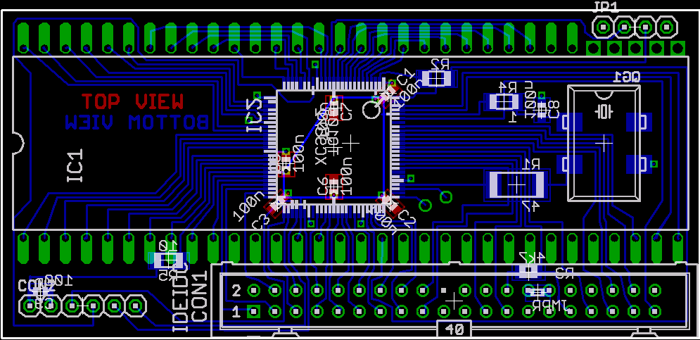
| pcb image | png
| png
| png
| png
| png (1)
| png
| png
| png
| png
| png
| png
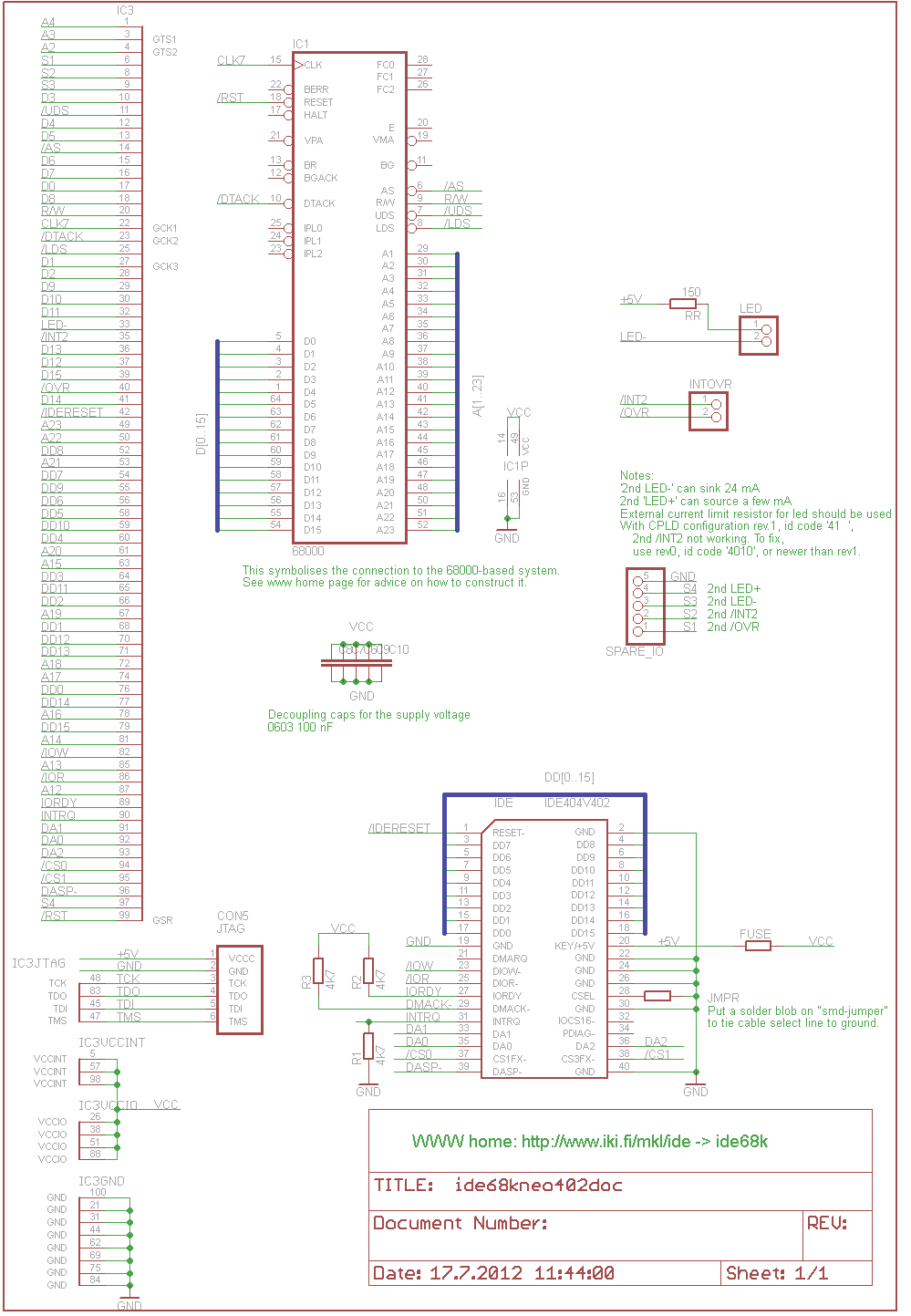
| schematic
| png ps
| png ps | png ps
| png
| png
| png
| png
| png
| png
| png
| png
| CPLD code
| JEDABL
| JED ABL
| JED ABL
| ii68-4027.abl excuse the misleading number for v29x code
| ii68-4025.jed ii68-4025.abl
| | |||||||||||