
![]()
![]()
![]()
![]()
![]()
![]()
|
|
|
This is a National NC-300. The dream of many a boy back in 1956. This is a 13 tube chassis plus one for the crystal calibrator option. Receive modes include CW, AM and SSB. This unit in for restoration is a fine well taken care of example.All relevant documentation may be found on BAMA.
Documents include the operator's manual and National Service Bulletins that
include several important revisions. Go to his free site to see the detailed
documentation.
|
| Reserved for front shot. |  Before cleaning.
 |
 Clorox Cleanup, Tooth brush and a rag.
 |
 Clean behind your ears too.
 |
 |
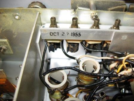 Date of manufacture on the oscillator shield. Resistor replacement
will be time consuming with all those leads. Use Carbon comps ONLY
before the IF!.
Date of manufacture on the oscillator shield. Resistor replacement
will be time consuming with all those leads. Use Carbon comps ONLY
before the IF!. |
 All replacement resistors inside the shielded box will be carbon
composition. The highest frequency after the 2nd converter is 2.295
mhz. Carbon films are OK.
All replacement resistors inside the shielded box will be carbon
composition. The highest frequency after the 2nd converter is 2.295
mhz. Carbon films are OK. |
 Homebrew 100 khz crystal oscillator/calibration unit.
 |
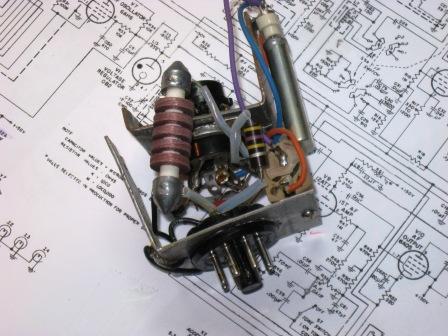 It
is beat up but it works!. I will check its stability. It
is beat up but it works!. I will check its stability. |
 Oscillator Ballast tube. I will look for a solid state replacement
for this ballast tube. Save this ballast tube for Show and
Tell. It will burn up and it is made of "Unobtainium".
Oscillator Ballast tube. I will look for a solid state replacement
for this ballast tube. Save this ballast tube for Show and
Tell. It will burn up and it is made of "Unobtainium". |

The base of the first mixer is obstructed by the trimmer caps. |
 The nuts were removed and the screws hotmelt tacked in to the holes.
 |
 Now that makes for an easy resistor replacement. Carbon comps only!
 |
 Screws stay in place.
 |
 Nuts are next. This was a whole lot easier than the oscillator
section.
Nuts are next. This was a whole lot easier than the oscillator
section. |
 Tell tail signs of a modification. Clear spaghetti. National
used black lacquered fabric. See the unsoldered connector on
tube socket pin 2. That probably created some frustration!
Tell tail signs of a modification. Clear spaghetti. National
used black lacquered fabric. See the unsoldered connector on
tube socket pin 2. That probably created some frustration! |
 Surprise! L6 has been replaced with a crystal. The NC303 has a
crystal in place of this coil.
Surprise! L6 has been replaced with a crystal. The NC303 has a
crystal in place of this coil. |

Not bad. |
 This frequency lines up with the appropriate side band for the band.
No USB available on 40 and 80 for digital modes. Hey! there was no
Ham digital in 1956.
This frequency lines up with the appropriate side band for the band.
No USB available on 40 and 80 for digital modes. Hey! there was no
Ham digital in 1956. |
 Installed with color coded wires. Green for control grid, yellow for
cathodes and black for ground. Yes this is not the National
black spaghetti. But this is a mod.
Installed with color coded wires. Green for control grid, yellow for
cathodes and black for ground. Yes this is not the National
black spaghetti. But this is a mod. |
 This radio is finished and receiving SSB on 160m.
 |
 |
 |
 |
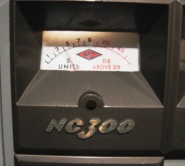 The needle is a bit fuzzy while swinging to the SSB modulation.
 |
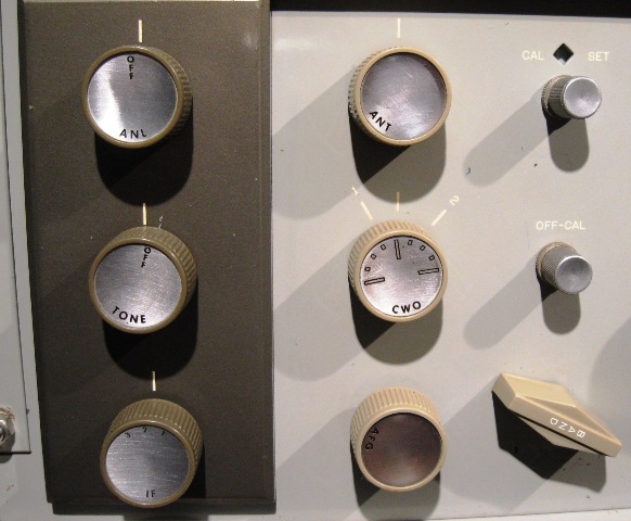 Starting settings to receive SSB
 |
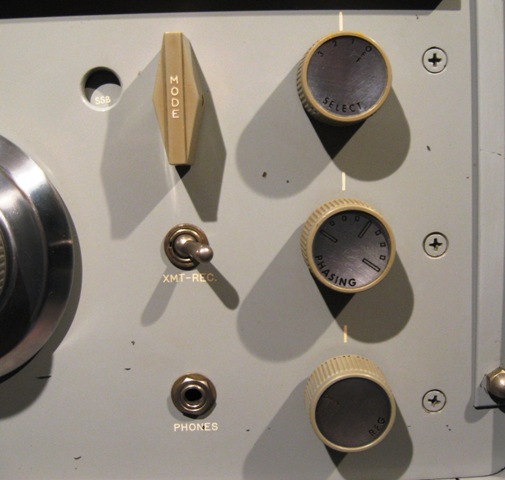 Starting setting for SSB.
 |
 |
 |
FSNs incorporated in this restoration (found on BAMA):
FSN-33 Replaced previously installed "revision" coax with properly
measured RG-174.
FSN-36 p1 Shielded cable from V2-9 to T3 B+ installed
FSN-36 p2 installed previously
FSN-36 p3 Antenna input coils not modified. This is to better match a 50 ohm
coax feed.
FSN-36 p3 modify antenna coils to better match 50 coax NOT done. May risk
destroying antenna coils for little gain.
FSN-37 p2 RG-174 coax used in FSN-33 and -36.
FSN-37 p3 changing 1 pf cap to 1/2 pf cap NOT done. 1/2 pf is too close to stray
capacitance to make a noticeable performance change.
FSN-41 replace 4H4-c ballast tube wit 6V6. Tube available for install
FSN-48 Second conversion coil replaced previously with 2295 kHz Crystal.
Replaced all resistors with FSN specified values.
Contact me including your thoughts and comments. 135,912 unique web site visitors (14,499,000 hits) from October 2004 through August 2011. Copyright © 2004 - 2012. All rights reserved.
|

