![]()
![]()
![]()
![]()
![]()
|
|
|
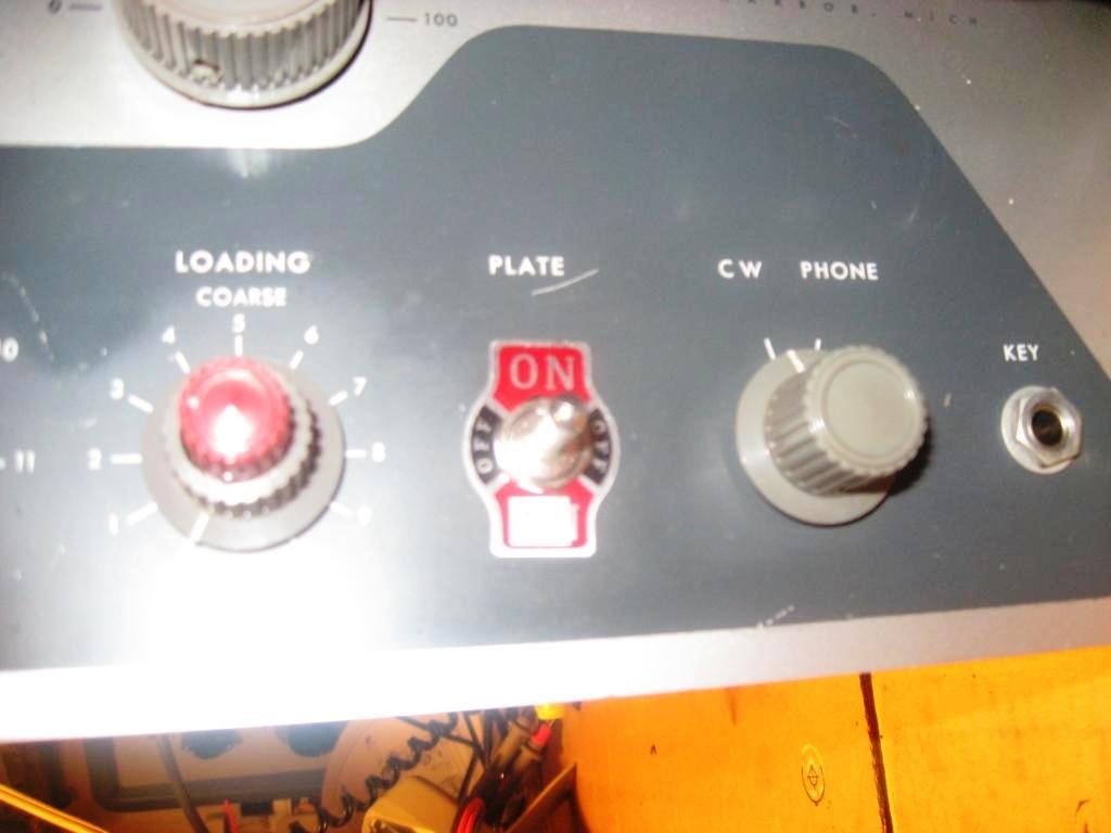
DX-100 Transmitter
Time to restore a wonderful Heathkit DX-100. All the tubes test good on an emission tester. And all the transformers test good too. There are some unidentified modifications. But that is expected with Ham gear. That is one way us hams learn, by trying things out.The HV and filament transformers are checked with a 12 volt ac wall wart. That holds down the secondary voltages and provides a little magnetic coupling for an "active" test. Just one more test beyond a DC ohm meter windings check.I am gathering documentation so the circuit can be put back to original. A parts inventory will be taken from the documents and a parts order placed. I measured on of the 1 watt carbon composition resistors. It was quite high out of tolerance. So the whole chassis will get fresh resistors along with a compliment of electrolytic and paper caps replaced.
AM testing went well with an HP 239A audio signal generator input. 100% modulation was achieved with about 1 to 2 volts input from the generator. There is a Stancor WF-20 input transformer driving the 1625 modulation tubes with a frequency response of 30-20khz HiFi. It has several input impedances available from 50 to 600 ohms. The output impedance is 50k ohms. The original transformer needs to supply around 93kohms impedance to the 12BY7 audio stage. Therefore, this Stancor transformer needs a hot line level input and frequency shaping to keep in the ham allocated bandwidth.
Bench testing into a 50 ohm dummy load.
| ||||||||||||||||||||||||||||||||||||||||||||||||||||||||||||||||||||||||||||||||
Contact me including your thoughts and comments. 135,912 unique web site visitors (14,499,000 hits) from October 2004 through August 2011. Copyright © 2004 - 2012. All rights reserved.
|