![]()
![]()
![]()
![]()
![]()
|
|
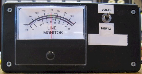
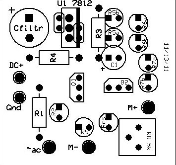
Line Voltage MonitorOrdering is closed for this Elmer Project.Listen in to the K3MJW Thursday night net at 9pm 146.640 neg offset pl 131.8.From the November 2010 QST p43 and May 2011.This is a 2011 Skyview, Solder Smoke Elmer Night project.Date October 25, 2011.Kit Builders: Bring your soldering irons and hand tools. There are five kit builders.
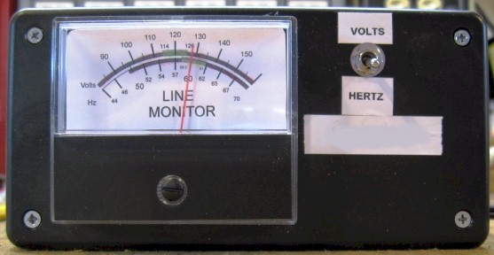
The Prototype is complete and fully operational!
I need your money before I order. The meter comes from China and the rest of the parts are for all intensive purposes non returnable.
Miscellaneous parts not included (hook up wire, hardware, grommets, etc).
Below is an additional circuit from Page 41, May 2011 QST. This will add Line Monitor Frequency Display capacities to the above project.
Junk Box Line Frequency Meter
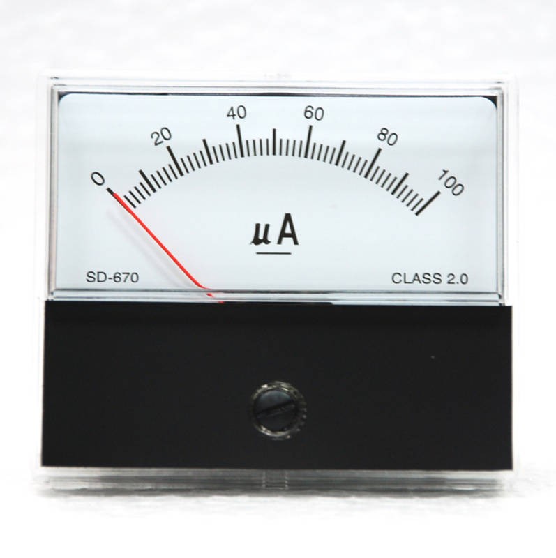
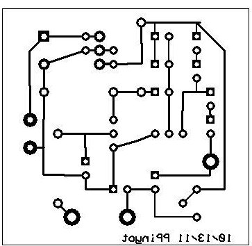
I am hoping to combine this circuit with an additional circuit from a few month later article in May 2011 QST. The Junk Box Line Frequency Meter. It displays the line frequency on a compressed scale. It seems to be a good add on for the above circuit. Below I am detailing the prototype.This circuit is to be build on a perf proto board. It is similar to a PC board except there are no traces to make intra component connections. The builder has to use additional wire to make up the circuit traces.A DPST toggle switch chooses from Volts or Frequency on the meter. So far the one problem has been the selection of a meter box. It appears not to accommodate both circuit boards. Additionally it seems on evening at Geeks Peak will not be enough time to complete both circuits.Both of the circuits Volt meter and Freq meter have been bread board prototyped and work great. This is where I determined the custom resistances needed as per the articles. This is where also the 100ua meter movement shunt resistor was determined to accommodate the 10ma Freq Meter architecture.
Some in progress pictures....
There are some minor pc trace image errors. But nothing that can not be overcome by careful placement and soldering of components.
Box details.
Meter Scale detail.There are some issues to be worked out. I want to print this scale in color but I have no functioning color printer. So I am trying to print to a PDF file but that is not going so well.
Using the meter in PA
I looked up some
documents:
| |||||||||||||||||||||||||||||||||||||||||||||||||||||||||||||||||||||||||||||||||||||||||||||||||||||||||||||||||||||||||||||||||||||||||||||||||||||||||||||||||||||||||||||||||||||||||||||||||||||||||||||||||||||||||||||||||||
Contact me including your thoughts and comments. 135,912 unique web site visitors (14,499,000 hits) from October 2004 through August 2011. Copyright © 2004 - 2012. All rights reserved.
|