The Apple Mac is an icon of the computer age. In the DOS ages, it pointed the way to how much better things could be. It was monochrome and modest, but it was to the 68000 what the ZX80/81 was to the Z80.
| CPU | An 8-MHz 68000 |
| RAM | 128Kbytes |
| ROM | 64Kbytes |
| MPX | Multiplexers |
| PALs | Programmable Array Logic |
| IWM | Integrated Woz machine |
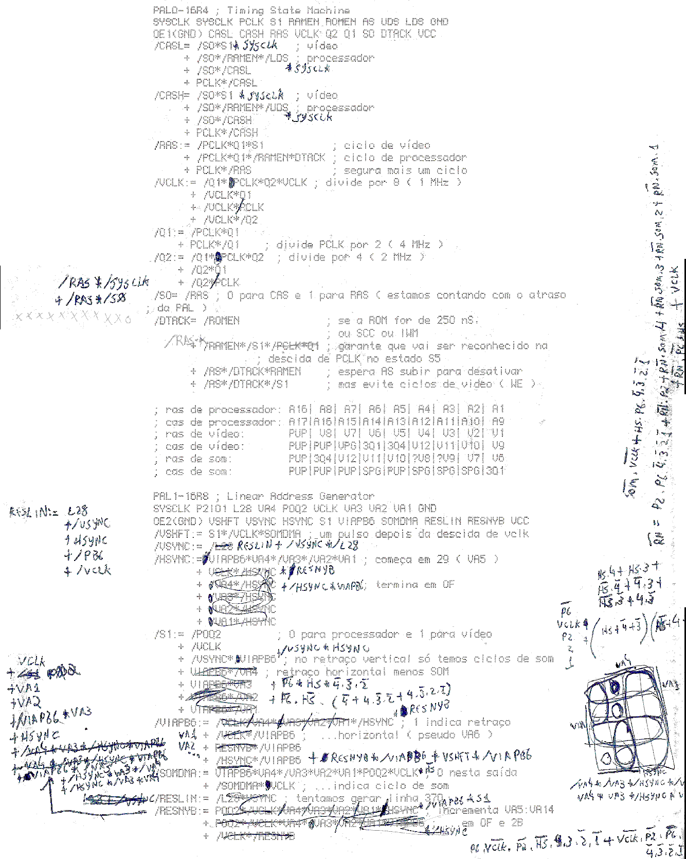
This page documents my peek into the dark logic of the PAL chips.
Translation from part of a report to Unitron about the Turbo Mac project. Translated by the author, Jecel Assumpcao Jr.
page 1 missing
page 2
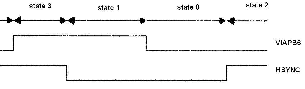
... frequency, but with different phases and duty cycles. The most intuitive way of understanding these sets it to consider them as indicating the current state for a finite state machine.
[drawing with VIAPB6 and HSYNC waveforms]
Basic Cycle:
We will call the interval between two successive loads of the video register "the basic cycle". It was exactly this cycle that was changed, such that all other changes were merely consequences of this. In the original design this cycle was divided into two memory cycles: one for the processor and the other for video. The change was the division of the basic cycle into three cycles for the processor and one for video. The timing of the basic cycle is the same: 16 cycles of the system clock (SYSCLK) which is equivalent to 1021 nS. During the horizontal retrace the video cycles would not be used and so are given back to the processor (except for the last, which is used to generate sound and to control the floppy drive speed). During the vertical retrace all cycles belong to the processor, except for the sound ones.
[drawing with SYSCLK, PCLK, original cycle and turbo cycle
waveforms] 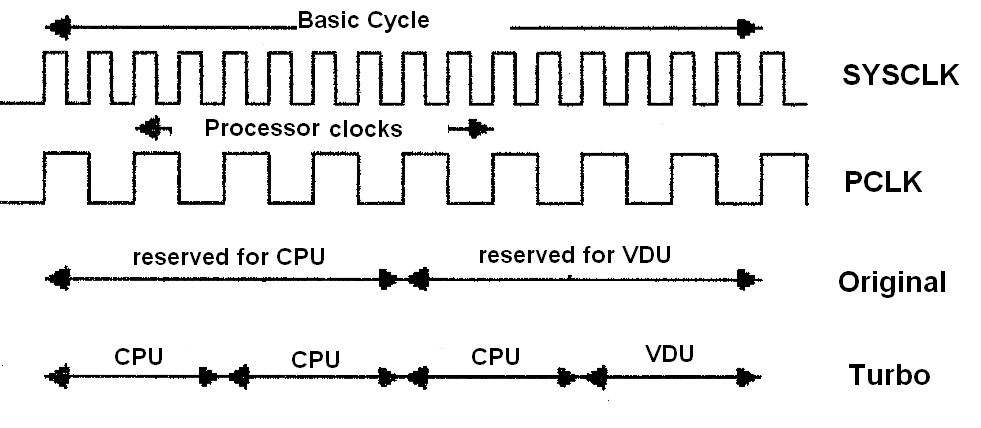
We can see that the memory cycle now takes up only half the time that it did before. The only was possible due to the evolution of the technology for dynamic memory chips: the 4164-15 originally used needed a cycles of at least 300 nS, while the 41256-12 has a cycle of 230 nS. The increase in performance of the Turbo relative to the original design comes from the possibility of having the memory sending more information to the processor in the same time period. At first glance it might seem that we can extract three times as much from memory, but looking at the duration of a processor cycle we see that it can't use too successive memory cycles. This and the fact that during the retraces and access to ROM the processor is the limiting factor reduces the gain in performance to about 20 to 30%. Let us look at the waveforms generated by the first PAL, which we will call here "Timing State Machine" or PAL0. It is the VCLK that defines the basic cycles, but let's examine each part:
[drawing with SYSCLK, PCLK, Q1, Q2, VCLK, S1 and VSHFT
waveforms] 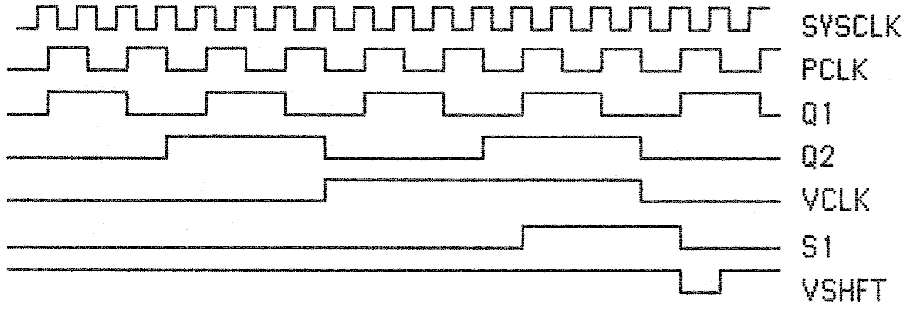
SYSCLK is generate directly from the 15.6672MHz oscillator and all other clocks are derived from it. But PCLK is generated in PAL4 and is used directly by the processor. Q1 has a cycle of 255 nS, since it is PCLK divided by 2. This signal defines the memory cycles in the Turbo Mac. Next we find Q2 and VCLK, which together with Q1 and PCLK form a sort of counter. It is obvious that these signals are not all in the same phase. VCLK and Q2 are three clocks early relative to the memory signals. The reason for this will become clear when VSHFT is explained. These two signals divide the basic cycle into four memory cycles. The memory cycle where Q2 is high and VCLK is high is reserved for video. The negative edge of VCLK, which happens halfway through this cycle, increments the video counters. When we look at CASH and CASL next, it might seem that the falling edge of VCLK would change the video address before the hold time (though only in the worst case considering component tolerances) but this doesn't happen because the column address for video comes from the most significant bits of the counter which are incremented by RESNYB.
------ all following pages are missing
I've just finished a first draft of re-drawing the Mac circuit in Orcad. It is just to get an idea of how it works. The ROM/RAM/CPU sections are not hard to fathom. There are a load of multiplexers for CPU/VDU/audio access, not so simple but you can see what it is up to. Most complexity lies in the PALs/IWM, but you can tell which PAL pins are definitely not outputs (those on the left of the chips.
I've managed to get an idea of what things are going on. Perhaps I could make a web page of my own scribblings? I don't know if I can be bothered to recreate the Mac, because the Atari ST is better (colour output, TV display, games). But maybe someone else is and would find my notes helpful
These should give you an idea of how to use PALs with the 68000. You will have to modify them for the Apple Mac
Page 222 Introduction
Page 223
Page 224
Page 225
Page 226
Page 227 PAL1 (20L10) logic equations, (OCR text)
Page 228 PAL1 (20L10) fuse map,
Page 229 PAL2 (16R4) logic equations, (OCR text)
Page 230 PAL2 (16R4) fuse map
Page 274 PAL (20X10) logic equations, (OCR)
Page 275 Function table,
Page 276 Description
Page 277 Fuse map
Page 278 Circuit
By Jecel Assumpcao Jr. for the now defunct Unitron of Brazil.
Unitron logic equations (1)
Unitron logic equations (2)
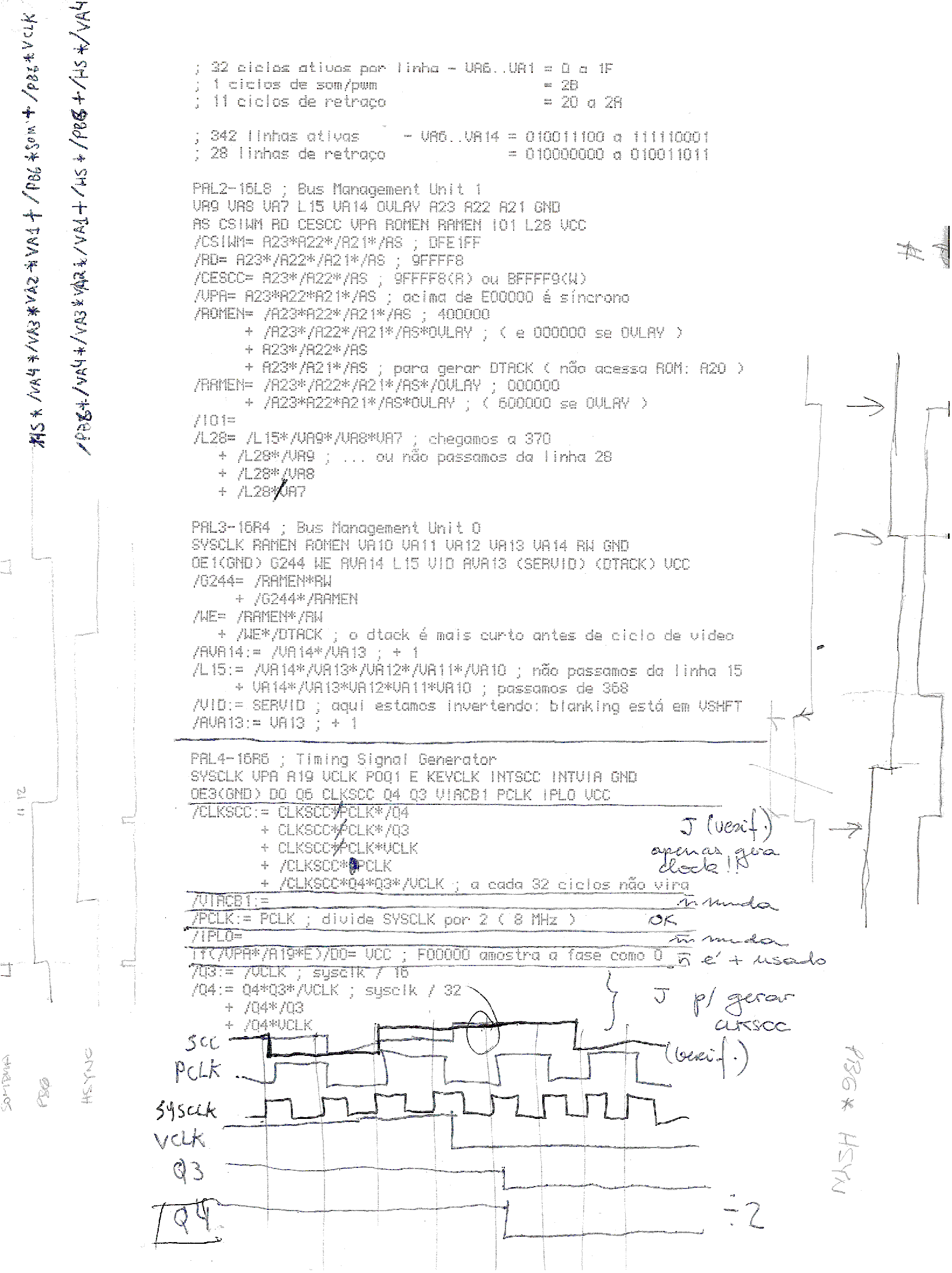
; 32 ciclos ativas par linha - VA6..VA1 = 0 a 1F  {32 active cycles per line}
; 1  ciclos de som/pwm                  = 2B      { 1 cycle  per ???/PWM}
; 11 ciclos de retraco                  = 20 a 2A {11 cycles retracing}
; 324 linhas ativas      - va6..va14 = 010011100 a 111110001  {324 active lines}
;  28 linhas de retraco              = 010000000 a 010011011   {28 cycles retracing}
PAL2-16L8 Bus management Unit 1
VA9 VA8 VA7 L15 VA15 OVLAY A23 A22 A21 GND
AS CSIWM RD CESCC VPA ROMEN RAMEN IO1 L28 VCC
/CSIWM = A23 *  A22 * /A21 * /AS ; DFE1FF
/RD    = A23 * /A22 * /A21 * /AS ; 9FFFF8
/CESCC = A23 * /A22        * /AS ; 9FFFF8(R) or 9FFFF9(W)
... not done yet...
library IEEE;
use IEEE.STD_LOGIC_1164.ALL;
use IEEE.STD_LOGIC_ARITH.ALL;
use IEEE.STD_LOGIC_UNSIGNED.ALL;

--  Uncomment the following lines to use the declarations that are
--  provided for instantiating Xilinx primitive components.
--library UNISIM;
--use UNISIM.VComponents.all;

entity AppleMac is
    Port (
			clk	: in std_logic;
			-- address and data buses
			A : in std_logic_vector(23 downto 1);
			D : inout std_logic_vector(15 downto 0);
			-- asynchronous control
			n_AS,			-- address strobe
			n_UDS,			-- upper data strobe
			n_LDS 			-- lower data strobe
					: in std_logic;
			n_DTACK : out std_logic;

			-- processor status
			FC : in std_logic_vector(2 downto 0);
			-- interrupt control
			n_IPL			-- interrupt priority level
			: out std_logic_vector(2 downto 0);
			n_INTACK : out std_logic_vector(7 downto 1);
			RNW : in std_logic;
			-- arbitration control
			n_BR : out std_logic;		-- bus request
			n_BG : in std_logic;		-- bus grant
			n_BGACK : out std_logic;	-- bus grant acknowledge
			-- 6800 peripheral control
			E : in std_logic;
			n_VMA : in std_logic;		-- valid memory address
			n_VPA : in std_logic;		-- valid peripheral address
			-- system control
			n_BERR : in std_logic;		--  bus error
			n_RESET : in std_logic;		-- reset
			n_HALT : inout std_logic;	-- halt
			-- non-CPU signals
			--
			OSC_in  : in  std_logic;
			OSC_out : out std_logic;
			CLK_CNT : out std_logic_vector(3 downto 0);
			n_IRQ : in std_logic_vector(7 downto 1)
			);
end AppleMac;
architecture Behavioral of AppleMac is
	----------------------------------------
	signal
		-- internal regs:
		-- write:
		s_clk_cnt		-- clock counter
		: std_logic_vector(3 downto 0);
	----------------------------------------
begin
	----------------------------------------
	-- inverter for simple crystal oscillator
	process (  OSC_in
	) is
	begin
		OSC_out <= not OSC_in;
	end process;
 	----------------------------------------
	-- clocked counter
	-- clk is about 16 MHz, so
	-- CLK_CNT(0) = 8 MHz,
	-- CLK_CNT(1) = 4 MHz,
	-- CLK_CNT(2) = 2 MHz,
	-- CLK_CNT(3) = 1 MHz.
	-- Zilog 8500 peripherals typically run at 	PLCK = 4 MHz
	--
	process (  clk, s_clk_cnt
	) is
	begin
		if rising_edge(clk)
		and n_RESET = '1'
		then
			s_clk_cnt <= s_clk_cnt-1;	-- decrementing
		end if;
	end process;
	----------------------------------------
	CLK_CNT <= s_clk_cnt;
	----------------------------------------
	-- INTACK generation and vector output
	-- Interrupt vector is 8 bits but
	-- this logic just encodes 3 of them.
	-- A(8 downto 4) can be pulled up with resistors.
	process (  n_AS, A, D, FC
	) is
	begin
		if	n_AS = '0'
		and	FC = "111"
		then	D(2 downto 0) <= A(3 downto 1);
			case A(3 downto 1) is
			when "000" => n_INTACK <= "1111111";
			when "001" => n_INTACK <= "1111110";
			when "010" => n_INTACK <= "1111101";
			when "011" => n_INTACK <= "1111011";
			when "100" => n_INTACK <= "1110111";
			when "101" => n_INTACK <= "1101111";
			when "110" => n_INTACK <= "1011111";
			when "111" => n_INTACK <= "0111111";
			when others =>
				null;
			end case;
		else
			D(2 downto 0)	<= "ZZZ";	-- tristate
			n_INTACK	<= "ZZZZZZZ";	-- tristate?
		end if;
	end process;
	----------------------------------------
	--
	-- interrupt priority level encoding
	process (  clk, n_AS, FC, n_IRQ
	) is
	begin
		if rising_edge(clk)
		then
			case n_IRQ is
			when "1111111" => n_IPL <= "111";
			when "1111110" => n_IPL <= "110";
			when "111110-" => n_IPL <= "101";
			when "11110--" => n_IPL <= "100";
			when "1110---" => n_IPL <= "011";
			when "110----" => n_IPL <= "010";
			when "10-----" => n_IPL <= "001";
			when "0------" => n_IPL <= "000";
			when others    => null;
			end case;
		end if;
	end process;
	----------------------------------------
	-- n_DATACK generation
	process (  clk, n_AS, FC, n_IRQ
	) is
	begin
		if	n_AS = '0'
		and	FC = "111"
		then
			case n_IRQ is
			when "0------"	=>	n_DTACK	 	 <= 'L';
			when others	=>	n_DTACK	 	 <= 'Z';
			end case;
		else
			n_DTACK	 	 <= 'Z';
		end if;
	end process;
	----------------------------------------
	----------------------------------------
	----------------------------------------
	----------------------------------------

end Behavioral;