- Contact Us
- |
- TI Worldwide: United States
- |
- my.TI Login
|
|
Hardware Tools
Software Tools Web Resources |
Content of the FET ToolsContent of the FET tools is mostly similar apart from the Board and the ICs. So in each Kit are the following parts included. What's Included
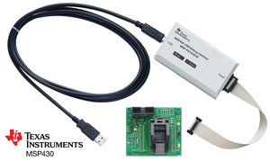
MSP-FET430U14 View ImageThe debugging tool interfaces the MSP430 to the included integrated software environment and includes code to start your design immediately. The MSP-FET430U14 development board supports all MSP430 flash parts in a 14-pin TSSOP package (TI package code: PW).
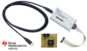
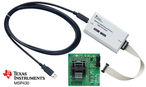
MSP-FET430U28 View ImageThe debugging tool interfaces the MSP430 to the included integrated software environment and includes code to start your design immediately. The MSP-FET430U28 development board supports all MSP430 flash parts in a 20- or 28-pin TSSOP package (TI package code: PW).
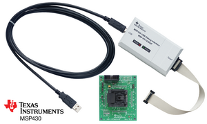
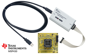
MSP-FET430U23x0 View ImageThe debugging tool interfaces the MSP430 to the included integrated software environment and includes code to start your design immediately. The MSP-FET430U23x0 development board supports all MSP430F23x0 flash parts in the 40-pin QFN (RHA) package.
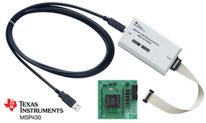
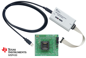
MSP-FET430U38 View ImageThe debugging tool interfaces the MSP430 to the included integrated software environment and includes code to start your design immediately. The MSP-FET430U38 development board supports all MSP430 flash parts in a 38-pin TSSOP package (TI package code: DA).
MSP-FET430U48 View ImageThe debugging tool interfaces the MSP430 to the included integrated software environment and includes code to start your design immediately. The MSP-FET430U48 development board supports all MSP430 flash parts in a 48-pin SSOP package (TI package code: DL).
MSP-FET430U64 View ImageThe debugging tool interfaces the MSP430 to the included integrated software environment and includes code to start your design immediately. The MSP-FET430U64 development board supports some MSP430 flash parts in a 64-pin LQFP package (TI package code: PM), except for the MSP430F41x2 devices. For the MSP430F41x2 devices, see the MSP-FET430U64A development board.
MSP-FET430U64AThe debugging tool interfaces the MSP430 to the included integrated software environment and includes code to start your design immediately. The MSP-FET430U64A development board supports some flash parts in a 64-pin LQFP package (TI package code: PM). For other 64-pin MSP430 devices, see the MSP-FET430U64 development board.
MSP-FET430U80 View ImageThe debugging tool interfaces the MSP430 to the included integrated software environment and includes code to start your design immediately. The MSP-FET430U80 development board supports some MSP430 flash parts in an 80-pin LQFP package (TI package code: PN), except the MSP430F552x and MSP430F551x. For the MSP430F552x and MSP430F551x devices, see the MSP-FET430U80USB development board.
MSP-FET430U80USBThe debugging tool interfaces the MSP430 to the included integrated software environment and includes code to start your design immediately. The MSP-TS430PN80USB development board supports development with all MSP430F552x Flash devices in a 80-pin LQFP package (TI package code: PN).
MSP-FET430U100 View ImageThe debugging tool interfaces the MSP430 to the included integrated software environment and includes code to start your design immediately. The MSP-FET430U100 development board supports some MSP430 flash parts in a 100-pin LQFP package (TI package code: PZ), except the MSP430F471xx and the MSP430F543x. For the MSP430F471xx, see the MSP-TS430PZ100A development board. For the MSP430F543x, see the MSP-FET430U5x100 development board.
MSP-FET430U100AThe debugging tool interfaces the MSP430 to the included integrated software environment and includes code to start your design immediately. The included MSP-TS430PZ100A development board supports all MSP430F471xx flash parts in a 100-pin LQFP package (TI package code: PZ). The 100-pin socket target board (MSP-TS430PZ100A) is also available standalone without the additional debugging interface.
MSP-FET430U5x100 View ImageThe debugging tool interfaces the MSP430 to the included integrated software environment and includes code to start your design immediately. The included MSP-TS430PZ5x100 development board supports all MSP430F5xx flash parts in a 100-pin TQFP package (TI package code: PZ). The 100-pin socket target board (MSP-TS430PZ5x100) is also available standalone without the additional debugging interface.
FET430F6137RF900The FET430F6137RF900 is a complete wireless development tool for the CC430 that includes all the hardware required to develop an entire wireless project. The sample kit includes two sub-1GHz wireless target boards (including antennas) featuring the highly integrated XCC430F6137IRGC RF System-on-chip. Projects may be developed and instantly deployed using the included batteries. Note: the current version (v3.1) of the tool supports 868/915 MHz operation only. The CC430 integrates the latest MSP430F5xx core (which combines 25 MHz performance with a 200-ksps 12-bit ADC, AES hardware security module and a 96 segment LCD driver) with theCC1101 multi-channel RF transceiver designed for low-power wireless applications. The EM430F6137RF900 board development included in this kit supports all CC430F613x and CC430F612x flash parts in the 64-pin QFN (RGC) package. It also supports software development for the CC430F513x parts (48-pin QFN (RGZ) package). The SimpliciTI software stack (a proprietary low-power star network stack) for the CC430 will also be made available to interested developers, enabling robust wireless networks out of the box Disclaimers
A separate debugging and programming interface is required to work with the EM430F6137RF900. A flash emulation tool (FET) may be purchased independently (MSP-FET430UIF) or bundled with the EM430F6137RF900 (FET430F6137RF900). Features
| ||||||||||||||||||||||||||||||||||||||||||||||||||||||||||||||||||||||||||||||||||||||||||||||||||||||||||||||||||||||||||||||||||||||||||||||||||||||||||||||||||||
Products | Applications | Design Support | Sample & Buy ![]()
TI Worldwide | About TI | Contact Us | Investor Relations | Press Center | Corporate Social Responsibility | Careers | Tags | my.TI Login | All Searches | Site Map
© Copyright 1995-2008 Texas Instruments Incorporated. All rights reserved. Trademarks | Privacy Policy | Terms of Use


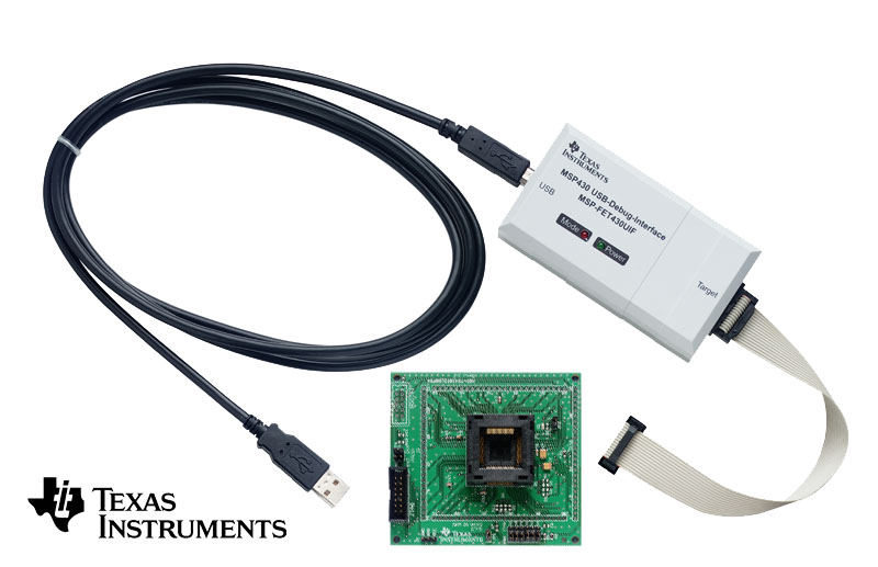
 Starter Kits come with everything required to complete an
entire project including a target board, USB debugging and
programming interface, free IDE software, MSP430 samples,
and cables. Most target boards include a socket for a
specific package and pin count. Please double check
the recommended tool for the device you intent to use on the
device's web page.
Starter Kits come with everything required to complete an
entire project including a target board, USB debugging and
programming interface, free IDE software, MSP430 samples,
and cables. Most target boards include a socket for a
specific package and pin count. Please double check
the recommended tool for the device you intent to use on the
device's web page.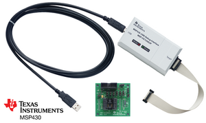