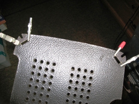
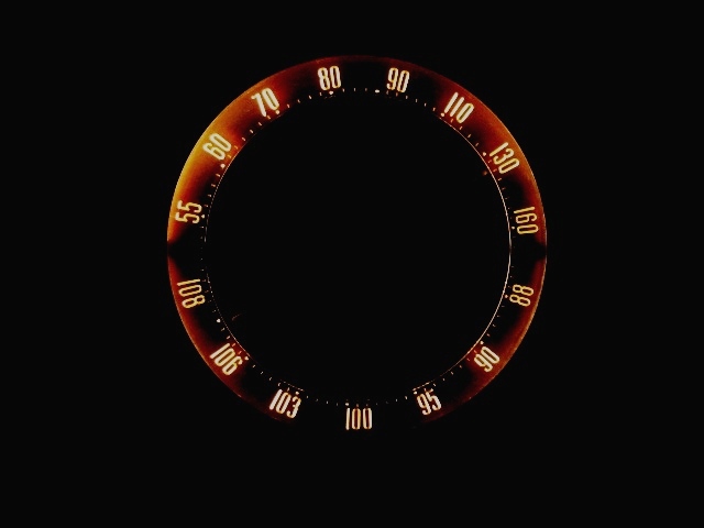
1-R-81


Home Up RCA 25BP Radiola 17 1-R-81


RCA 1R81

This is an RCA 1-R-81 chassis RC1102B or C.  This radio has coupling and electrolytic capacitors replaced.  But it poorly received only one FM station when received.  The bakelite exterior is in fantastic shape and needs no attention.  I proceeded with a complete restoration including all previous replaced parts.  The old caps are identified with a red mark.  
I began this restoration first with a dim bulb test.  Then all tubes tested including a spare set from the owner.  All non mica or ceramic capacitors, carbon composition resistors, lamps, speaker gasket and power cord set were then replaced.  Before the alignment I initially powered up the unit with a DBT.  It received well on both AM and FM.  With the alignment completed the radio receives very well on both FM and AM.  An external antenna connected to the #1 screw pulled in distant weak AM station at night.  The less powerful FM stations also benefits from an external antenna connected to screws #2 and 3.    I used a random wire on the FM.  An FM dipole (like this one from Radioshack) would help a lot. 
This radio has a pretty dial scale.  It has a symmetry that looks balanced and illuminates gently in a dimmed room. Please see the pictures below.
IMG_5025.JPG (1822497 bytes) IMG_5026.JPG (1785649 bytes) IMG_5027.JPG (1980070 bytes)

The right upper and lower cardboard retaining tabs need glued. 

IMG_5030clrcrct.JPG (1344016 bytes) IMG_5033.JPG (1489939 bytes) IMG_5037.JPG (1205773 bytes)
IMG_5034.JPG (1160017 bytes) IMG_5039.JPG (1583249 bytes) IMG_5045.JPG (1757764 bytes)

That is a replacement Audio Output transformer.

All original yellow caps received a red dot before I started replacing parts. 

IMG_5073.JPG (203271 bytes)

The yellow caps are not original equipment.

IMG_5046.JPG (198900 bytes) IMG_5040.JPG (1842361 bytes)

RF deck with covered underside. AM/FM IF leaves this section. 

IMG_5078.JPG (199081 bytes)

All resistor replaced with new Carbon Comp resistors. My little rule for part handling over 18 MHz. 

IMG_5079.JPG (194666 bytes)

All new caps and resistors installed. 

IMG_5082.JPG (169179 bytes) IMG_5085.JPG (113454 bytes) IMG_5087.JPG (161773 bytes) IMG_5088.JPG (138827 bytes)
IMG_5038.JPG (1358919 bytes)

Old gasket.

IMG_5080.JPG (144403 bytes)

New speaker gasket. It seals acoustic leakage that deteriorates frequency response.

IMG_5028.JPG (88905 bytes)

Glued torn corners. 

IMG_5093.JPG (167645 bytes)

Wood Glue and clamps. 

IMG_5092.JPG (153991 bytes)

Glued down loose stickers too (lower left only). 

rcadialscale.JPG (41202 bytes)

I like the night shots.


Hit Counter


 Contact me including your thoughts and comments. 

Please see the LINKS page.  I have collected many resources over the years.

135,912 unique web site visitors (14,499,000 hits) from October 2004 through August 2011.

Copyright © 2004 - 2012. All rights reserved.