
![]()
![]()
![]()
![]()
![]()
![]()
![]()
![]()
![]()
|
|
|
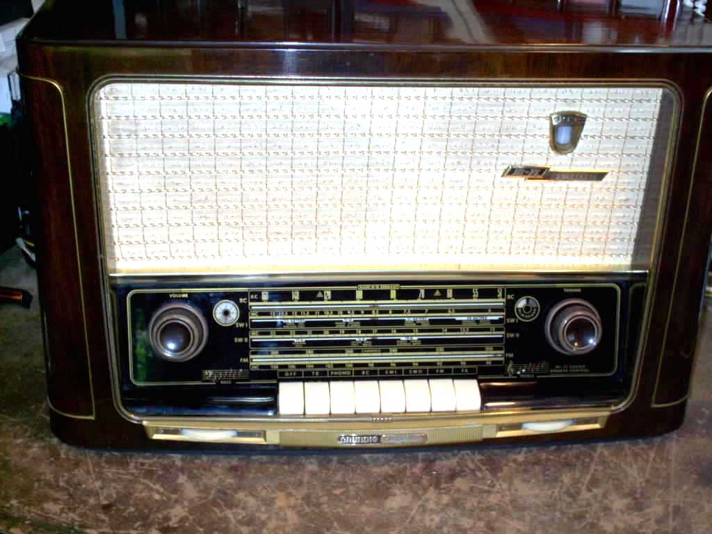
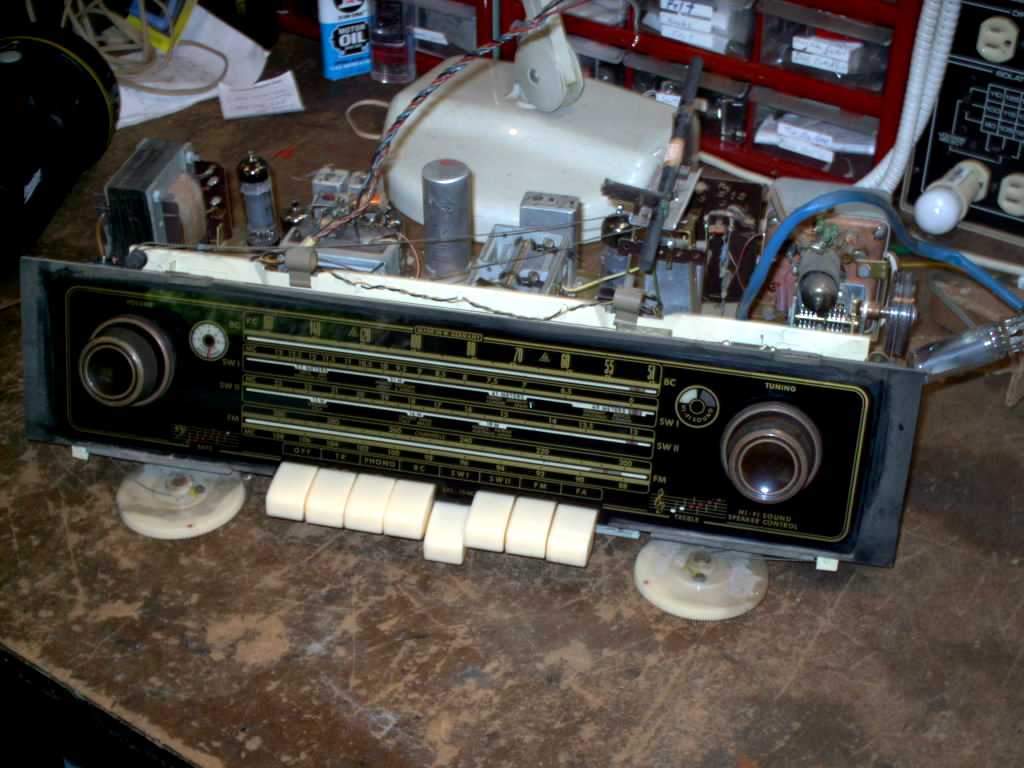
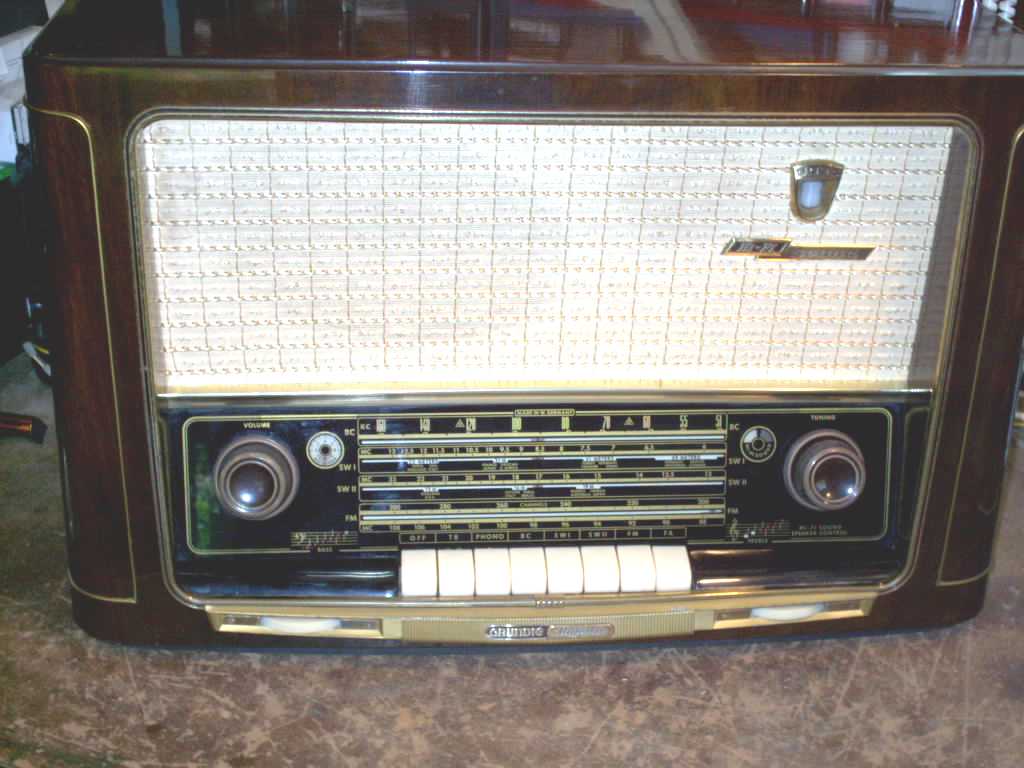
This is a 3055 with 3D sound USA Version. This case is in Excellent shape. Nothing needs done with the wood finish. The plastic parts were cleaned and treated with Glayzit. The Dial glass cleaned and the red line on the FM indicator repainted.
The original Eye tube is an EM-85 (6DH7). This has been replaced by an EM-81 that looks the same but with different pin outs. The specs of both tubes closely compare. The EM85 is hard to get and very expensive tube, if you can find one. Both popular vintage radio vendors that I do business with do not carry it. And I do not want to risk the likely probability of a re-marked or fake eBay purchase.
This is the second of two featured 3035s.
3035 w/3D USA
| ||||||||||||||||||||||||||||||||||||||||||||||||||||||||||||||||||||||||||||||||||||||||||||||
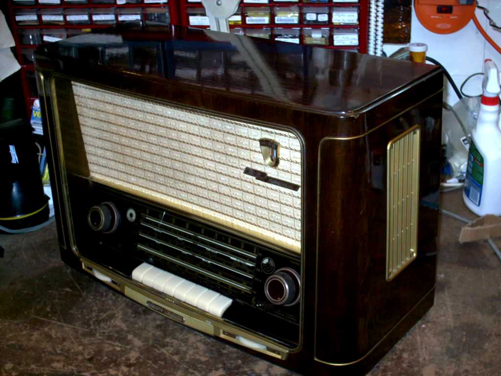
 As received
 |
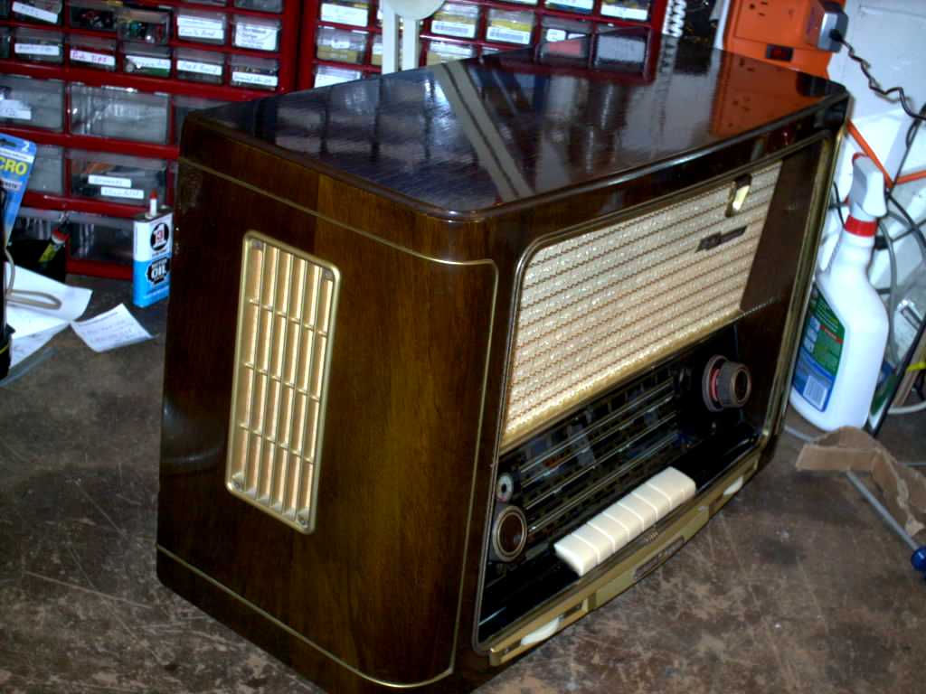 Look
left Look
left |
 Look right
 |
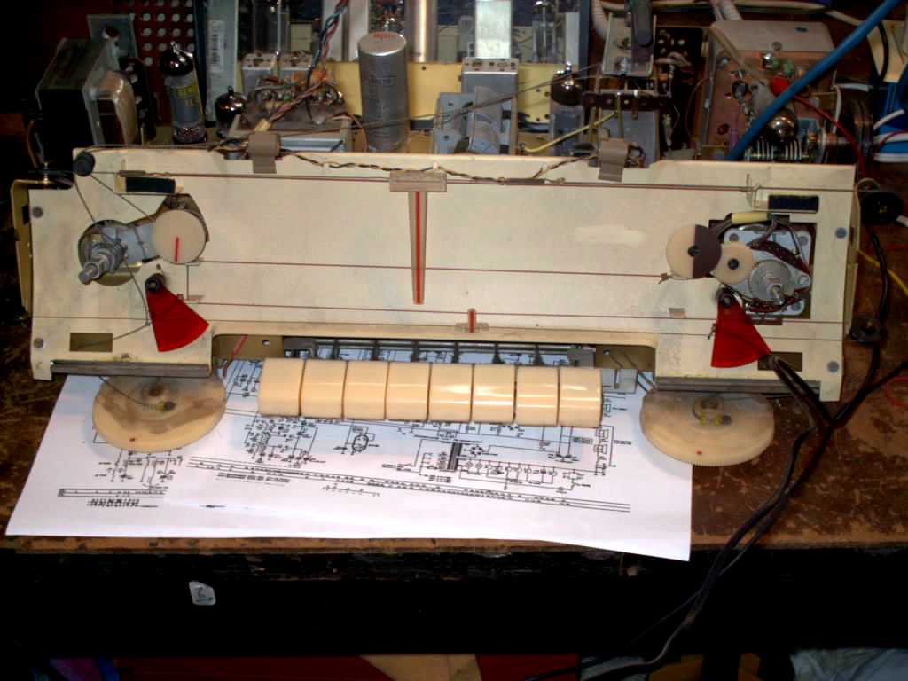
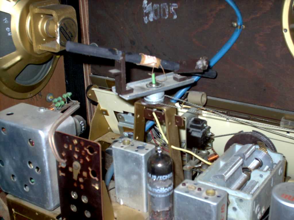 Broken Ferrite Antenna support quickly repaired with Hot Melt glue
gun. Replacing and stringing the dial cord was a different
matter.
Broken Ferrite Antenna support quickly repaired with Hot Melt glue
gun. Replacing and stringing the dial cord was a different
matter. |
 Out of the cabinet shot.
 |
 I ALWAYS store the dial glass separately. I do not want an accident
and have to find a replacement!
I ALWAYS store the dial glass separately. I do not want an accident
and have to find a replacement! |
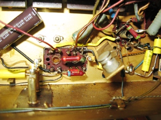
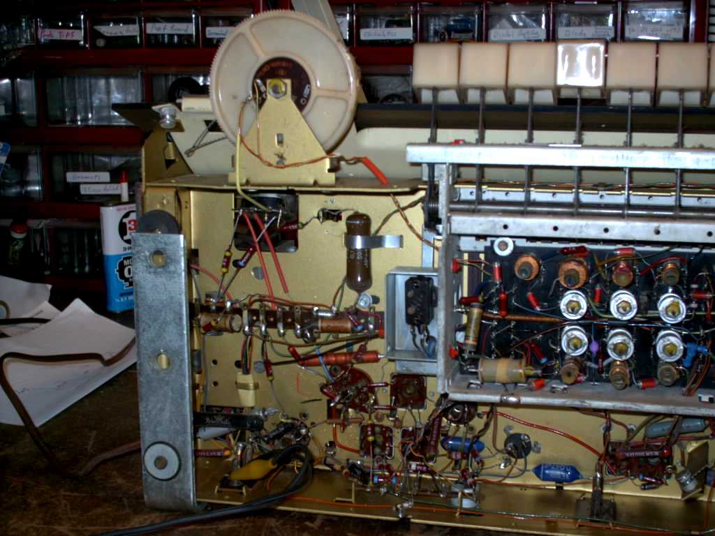 The blue capacitor just under the left side of the switch enclosure was
shorted. You can also see the burnt (open) 1k ohm resistors that the
short took out.
The blue capacitor just under the left side of the switch enclosure was
shorted. You can also see the burnt (open) 1k ohm resistors that the
short took out. |
 The
yellowed paper capacitors can be seen under side. The blue
capacitors are also paper inside. The
yellowed paper capacitors can be seen under side. The blue
capacitors are also paper inside. |
 Restored and working. Products on the left used to shine the knob brights
and treat the plastic. Glass cleaner took care of the dial
glass. TEST the paint before cleaning.
Restored and working. Products on the left used to shine the knob brights
and treat the plastic. Glass cleaner took care of the dial
glass. TEST the paint before cleaning. |
 No flash and Light Out shot.
 |
Sorry. I did not take a picture of the restored under chassis. I will post one if I disassemble the unit again. All the paper and blue capacitors have been replaced with yellow tubular caps that are considerable smaller in size but all rated at 630 volts. | In the picture directly above, between the two horizontally oriented blue caps, is a dark circle with three wires. Two electrolytic capacitors mounted to a new terminal strip replace the chassis mounted can capacitor. The wires were moved to the terminal strip and the can cap left in place for appearance sake. Again sorry for not taking an after picture. See the Capacitor Page for an example. |
 This is the flat pack selenium rectifier bridge removed from the
radio. A screw driver, pliers and a soft touch will slip the cover
off.
This is the flat pack selenium rectifier bridge removed from the
radio. A screw driver, pliers and a soft touch will slip the cover
off. |
 Once the cover clears the bottom metal container the top flies across the
table and little square metal pieces shower back down on your bench.
Those are the selenium wafers.
Once the cover clears the bottom metal container the top flies across the
table and little square metal pieces shower back down on your bench.
Those are the selenium wafers. |
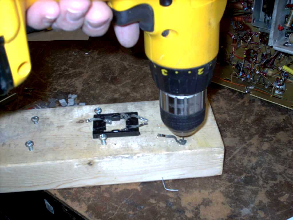 Trim the contacts so one pad per solder contact remains. Drill two
holes in each to receive the 1N4007 lead wires.
Trim the contacts so one pad per solder contact remains. Drill two
holes in each to receive the 1N4007 lead wires. |
 I tapes and labeled the solder pads in accordance to the stamped terminal
identifiers in the metal cover plate (the one that shot across the
bench).
I tapes and labeled the solder pads in accordance to the stamped terminal
identifiers in the metal cover plate (the one that shot across the
bench). |
 Install and solder all four diodes.
 |
 Reassemble making sure all the insulating materials are returned inside
the metal enclosure or a high voltage short will occur. That's it!
Reassemble making sure all the insulating materials are returned inside
the metal enclosure or a high voltage short will occur. That's it! |
 Schematic Diagram.
 |
 Front view.
 |
 Rear
view of switch box. Rear
view of switch box. |
 DIN connector in the Grundig 3035.
 |
![]()
See the photos below:

As Received. |

As Received (the flash lightened the cabinet color. |

Restored. |

Nice dial scale. And sounds great too! Trust me on this one. |

Cleaned with Deodorized Mineral spirits to remove wax, dirt and grime. |

Various stain pens used to darken chips and scratches. |

A coat of hand rubbed paste wax.... |

...and a nice buffing. |

She cleans up nicely. |
 |

Record the wiring point. |

Original parts |

Ugh, Dirt. |

Stuffed 1N4007 diodes inside the selenium bridge case. |

All B+ voltage right on the mark with the fuse at 125vac. No series resistor needed. |

The moving coil on this IF can will not move. Document wire connections before removing can. |

Yep. That's the culprit. Simple cleaning did not work. So it has to be repaired. |

No luck on the chassis so off it comes. This photo shows orientation of the transormer. |
 |

Those Germans sure know how to make an elegant IF transformers. |

The rod on the right is stuck. |
 |

A good flush does not work. |

Nor does a good scrubbing. |

Sand off the corrosion from the top of shaft, No go. |

Now for the drill bit. |

It scraped off some rough spots. |

The shaft now moves easily. This is Caig Fader Lube. |

This lube is used on slider pots. I works great on the brass to plastic interface. |

Just like new! |
It has been re-installed and works great with the treble control. It only retracts about 1/8 inch. |

All caps have been replaced, all resistors tested. |
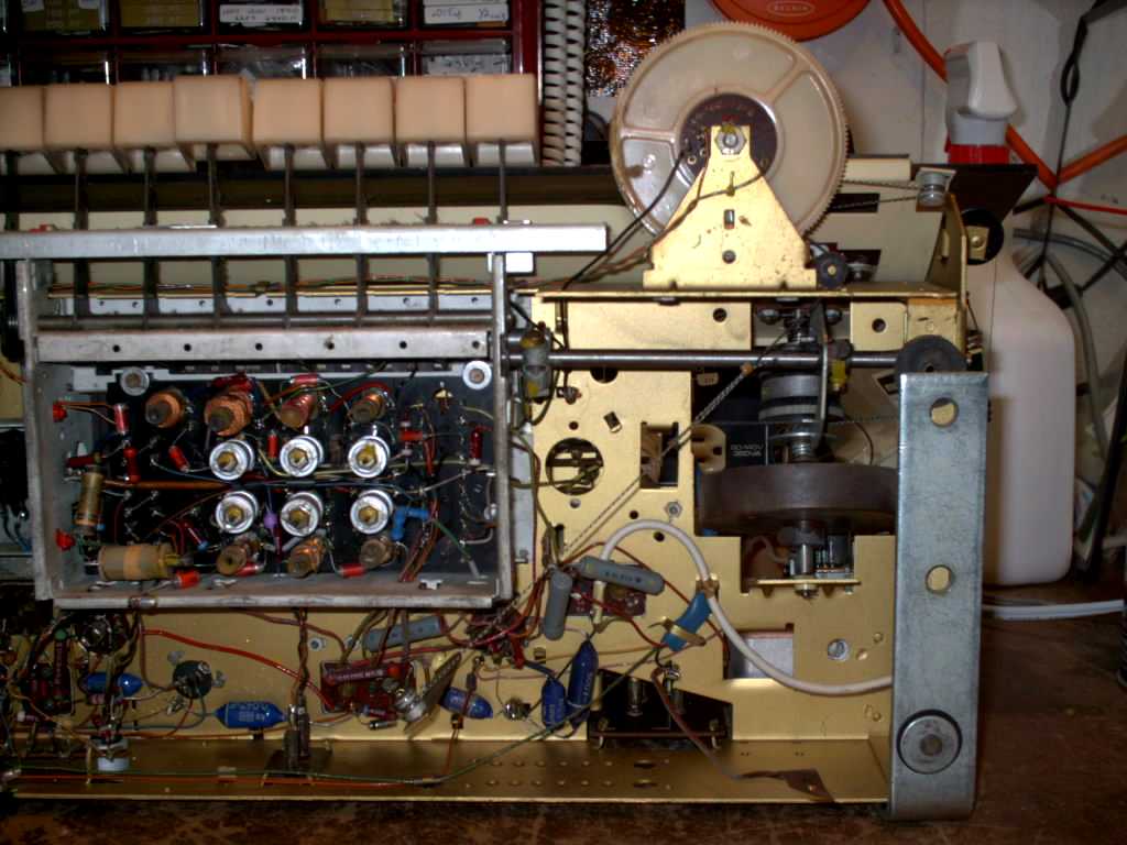
FM tuner
All good inside. I re-tensioned the tube socket. The pins were loose. |

Clean. No paper caps here. All resistors test good and in tolerance. |

This socket has been rewired to accommodate an EM80. The EM80 has the same electrical/performance specs as the original EM85. |

Time for a clean up! Wipe on Clorox Clean Up. |

This is a deep untreated scratch into the wood. It was darkened with a stain pen. |
The Tweeter received an internal overhaul.
You can't hear this picture but trust me, it sounds great! |

New plumber's washers used on the chassis retaining bolts. It isolates the metal chassis from the wood cabinet (a little bit). |

The speaker selector needed the wiper contacts burnished. Several on the chassis cleaning attempts did not get rid of an intermittent problem. It is all gone now! |
Contact me including your thoughts and comments. 135,912 unique web site visitors (14,499,000 hits) from October 2004 through August 2011. Copyright © 2004 - 2012. All rights reserved.
|


