Capacitor stuffing


Home Search Aetna Airline Atwater Kent. Bendix Blaupunkt Bogen Bowers Breting 14 Bulova Crosley Delco Dentron Electro-Neutronics Emerson Emud Fairbanks Morse Grant, W. T. Grebe Grundig Grunow Hammarlund Hallicrafters Heathkit Henry Hickok 288X Howard Howard Johnson Jesse French Johnson Korting Lafayette Lap Amp Motorola NAD National. Nordmende Norelco Packard-Bell Perpetuum-Ebner PHILCO Philips PYE P35 RCA Robyn T-123B SABA Silvertone 4663 Standard A Stewart Warner Telefunken Triplet 3436 vhf gen Wagner Walgreen WEGA Westinghouse Yaesu ZENITH Links Audio Reinforcement Antenna Cabinet Finishing Capacitor stuffing Comments Dial Scales Dim Bulb Tester Electrodynamic Electrostatic Elmer is his name. Etching Emblems IF Transformers Lead Twister Leakage Tester Packing Tips Resistors Rodent Damage Shiny Chassis Slides & Presentations Tube Analyzing Vendors Laptop


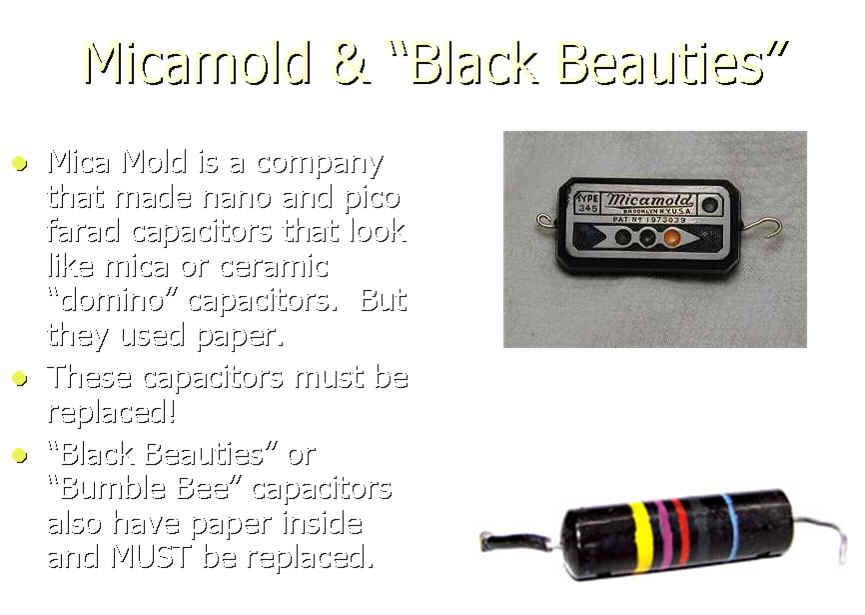
Old "cm" label conversion. 1cm = 1.1pf  See: http://www.radiomuseum.org/forum/old_capacitor_markings.html 


For an example of different capacitor types see this page.  


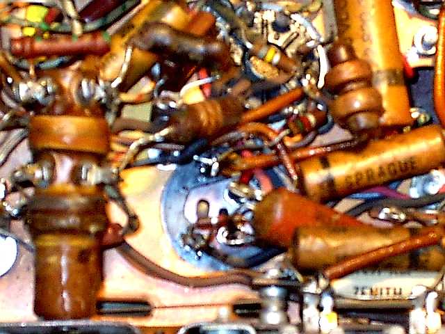
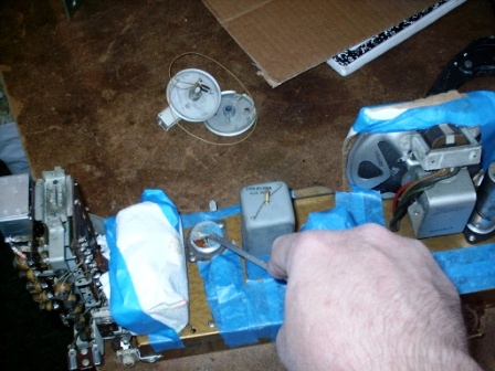
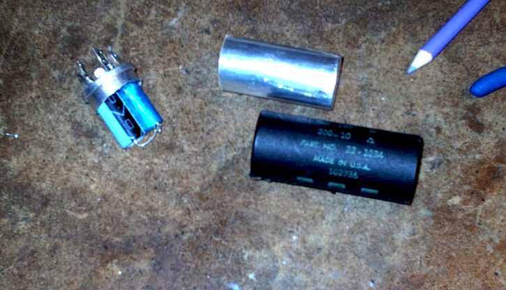
One of the first steps to a proper vintage tube radio restoration is replacement of old capacitors.  Typically the wax/paper and the electrolytic are "Shot-gunned" or wholesale replaced prior to any other troubleshooting or further restoration.  The old capacitors can be clipped out and new ones installed.  Or Re-stuffed.  

Re-stuffing a capacitor is the process of putting new internal components into the original capacitor shell.  Most typically this is done to the electrolytic can capacitors that are mounted to the top side of the chassis.  Most times the electrolytic capacitors are simply disconnected and abandoned in place.  New capacitors are installed under side of the chassis, out of site.

The original wax/paper capacitors may also be re-stuffed for a "Museum" quality restoration.  This is a very time consuming process usually reserved for the most precious of radios.  Most Wax/paper capacitors will never be seen unless the chassis is removed from the cabinet and flipped over.

When there is no space under the chassis for new electrolytic capacitors the original can may be "re-stuffed" with the new replacement capacitors.  These pictures below of a Zenith Transoceanic electrolytic capacitor showing the steps on how it is done. 


On Chassis - Twist Lock can capacitor restuffing.
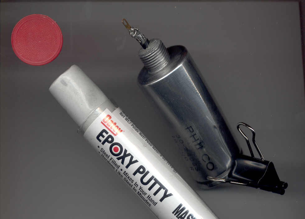
IM000010.JPG (122666 bytes)

This location in a Zenith Transoceanic is too cramped for additional capacitors. And this radio is very sensitive to component placement near the wire coils (bottom left tube).

heatcap a (1).JPG (68191 bytes)  heatcap a.JPG (67016 bytes)

Heating the black cardboard with a 40 watt lamp softens the black tar holding the cover on the can.  

No need for an expensive heat gun or a damaged hair dryer and an upset wife.

heatcap a (2).JPG (66753 bytes)

After even heating the cover it pulls free with little force.  Be careful not to break the can to chassis insulator.

Protect a.JPG (100605 bytes)The Dial cord and tuning pulleys have been removed to afford access.  

Plenty of tape and protection from hack saw hits and saw dust has been added.  A contaminated variable air tuning capacitor can be difficult to clean.

Hack Saw blade a.JPG (27468 bytes)A hack saw blade with out the handle is used with a light touch. 

 Sawing too hard risks cracking the capacitor to chassis insulator.

cut through a.JPG (61717 bytes)The capacitor has been cut through, exposing the plates and paper.  

This cap is quite dry.  Electrolytic capacitors typically have liquid electrolyte to enhance their capacity.

clean out a.JPG (65297 bytes)Clean out the remains. 


 Next, drill additional small holes for capacitor lead access.

new caps a.JPG (22769 bytes)Two of the caps have been labeled with the square and triangle symbol representing the multi-section can values.  

The new caps are hot melt glued in place for when the chassis is flipped and the lead wires soldered.

complete aJPG.jpg (69956 bytes)The speaker was un-bolted and swung clear to cut the right side can cap.  

Next the black cardboard covers were returned and secured with a small amount of hot melt glue around the base of the can.  A small amount was used to allow future service access.

A Twist Lock Can capacitor on the bench.


Remove capacitor by carefully unsoldering the wires and untwisting the locking tabs. 

 cut can.JPG (76849 bytes)

Heat and remove cardboard cover and cut the can open.


remove guts.JPG (106860 bytes)

Remove and discard old dried contents. Clip the lead wires, from the foil plate, level with the base.


Drill additional access holes in the can base to accommodate the new capacitor lead wires.

new caps.JPG (113324 bytes)

Install and hot melt glue in the new capacitors.  Solder the lead wires to the original solder lugs.


Re-assemble using hot melt glue.  

assemble glue.JPG (46256 bytes)

Reinstall the can and gently twist the locking tabs being careful not to snap them off.


Re-stuffing a can capacitor saves space and maintains the original vintage look above and below the chassis.


Stud can capacitors. (not restuffed)

Here is detail of a Philco capacitor.  The internal plates have been removed with a long needle nosed pliers.  The post was reinstalled with epoxy to be used as a binding post. This makes a convenient place to solder an external capacitor.  

Re-stuffing a capacitor is debatable when the conditions of; A) There is plenty of room under chassis and  B) The other replacement capacitors have not been hidden (re-stuffed) with in the original wax/paper capacitor wrapper.

Cut the stud out and remove internal plate.  Cut off the original insulator.  This one measured low resistance (for an insulator) on a DVM (about 2 meg).  stud_out.jpg (20218 bytes)

At full B+ there would be current flow and eventual dielectric breakdown.    There is absolutely no need to take such risk (carbon trail, short circuit) when simple fixes are available. 

epoxy.jpg (42244 bytes)  

This is great Epoxy purchased at Home Depot.  It hardens in minutes (like a rock) and has a spec for insulating capability!  

A salvaged terminal has been soldered to the stud to replace the original solder tab.  sideveiw.jpg (11850 bytes)

studveiw.jpg (30416 bytes)Stud replaced using Epoxy and a bit of heat shrink tubing.  This capacitor was reinstalled a Philco 40-150It is in the middle of the chassis with two red wires and a black electrolytic connected to it.


On the chassis  - Can capacitor replacement (not restuffed).

A terminal strip is used to mount the new capacitors and provide a convenient place to hook up wires.

 In the chassis can capacitor modification.

IM000052.JPG (69385 bytes) Step 1.  Remove center pin with pliers and insulator while can cap is in chassis.


IM000053.JPG (16804 bytes)Step 2. Straighten the mounting tab on a terminal strip.


IM000054.JPG (227756 bytes)  Step 3.  Push mounting tab in capacitor opening.


IM000055.JPG (69402 bytes)Step 4.  Mix up some Oatey plumber's epoxy and push into the hole.  


When the epoxy is hard connect up the wires and add new electrolytic capacitor.


 This is how the whole chassis looks with unstuffed can caps.

Finishedchassis.jpg (95293 bytes)

This is the restored chassis. Most of the wires were brittle and some were bare.  All paper/wax and electrolytic capacitors have been replace.  


Emud filter capacitor resuffing. 

From this radio click here.  This dual cap is rated at 350 volts.  Two of the 47uf 450 volt caps from Mouser fit.  


IMG_2881.JPG (154905 bytes) These are thin 450 volt 47uf caps.  See/order them here from Mouser. IMG_2882.JPG (126157 bytes)I used a pipe cutter to open this case.  The tape is to keep the aluminum from being scratched.  IMG_2883.JPG (136503 bytes)Make room. IMG_2887.JPG (104497 bytes)Drill little holes to line up with the solder tub studs (that you left in place!)  A third new wire and hole is needed for the ground.  Use the existing solder tab.  

Replace the cover with hot melt glue and bolt back in the chassis.  


1923 Grebe Syncrophase bypass condenser (capacitor).

IM000101a.JPG (85516 bytes) Careful heating on a low setting releases the wax.  

IM000103.JPG (184496 bytes)

B+ Bypass condenser measures 3.8 uf. 

IM000104.JPG (210432 bytes) These caps are replaced.  I would not want 90 or 135 volts on the old paper insulators.   The replacement is 450v.  A terminal strip is used for mechanical strength,  

IM000105.JPG (200761 bytes)

C+ bypass condenser about 3 uf (original).  This replacement is 160 v.  A much lower voltage  would have done fine.  These were abundantly in stock.

A little hot melt glue will adequately seal up these capacitors.  The tin exterior not shown is receiving a sprits of gloss black and a shellac top coat.   I will save the original internals in case an owner would like a 1920's cap. 


European Radio capacitor types.  

Another article about US resistor with pictures with a few European.


"Silver Mica Capacitor Disease"  in the IF transformer. 

If you hear a rushing, crackling or thunder storm coming from you speaker regardless of what band or frequency you tune to.  The volume typically quiets the noise when you turn the volume down.  Follow this hyperlink.


Don't forget the Bakelite blocks.  

Figure 1. A typical Philco Bakelite Block Consenser Click here Philco Radio for How To.  

Do you want to Re-stuff the Waxed Paper capacitors? 

  See this link to start.  

And how about those Dog gone Dog Bone Resistors?

    Try Syl's web site.  


Another link for caps  http://oldradio.ca:83/Radio/CapRestuff/restuff.html


Capacitor Life.


Make your own ESR?


Jump to this web site

.99 Cent ESR Test Adapter

http://octopus.freeyellow.com/esr.html

"Octopus" Oscilloscope Test Adapters

and more!


More Links of ESR interest:


http://members.shaw.ca/swstuff/esrmeter.html

http://alytus.auksa.lt/esr/

http://tinyurl.com/Creative-Labs-ESR-Meter

ftp://ftp.eskimo.com/u/m/mzenier/esrmeter.gif

http://tinyurl.com/iz7ath-ESR-Meter

...and here is a thread about the above projects:
http://tinyurl.com/sci-tech-archive-DIY-ESR

..And More

http://kakopa.com/ESR_meter/index.html

(I am going to make this one.)


ESR Adaptor. 

I built this ESR accessory (from http://octopus.freeyellow.com/esr.html) to be used with an oscilloscope and a generator.  It uses two resistor, three BNC connectors and one container.  I did add a switch with a 10 ohm and 1 ohm resistor across the capacitor lead connector.  This is used to set up the oscilloscope.

I have little call for retention of original capacitors.  However I also work on Ham Radio gear of relatively young age.  This gear does not always call for shot-gun replacement of capacitors. Another example is a Ten Tec 12vdc 18 amp regulated power supply (not shown).  It contains a 26,000 uf capacitor.   I prefer to keep this capacitor if it measures low ESR and good capacitance. 

I just do not see the need for a $150 digital ESR meter.  This adaptor does fine for my infrequent need to check ESR.  I may make one of the complete analogue units from the links above.  I can see how handy a portable ESR meter can be. 

IMG_2848.JPG (148467 bytes) All parts are from the "junk box" except the resistors.

IMG_2846.JPG (151295 bytes)  The banana plugs are parallel to the BNC

IMG_2845.JPG (150379 bytes) I incorporated two resistors on a switch for scope set-up.  

IMG_2832.JPG (182942 bytes) Open Circuit. The upper trace is unused except to mark the 10 ohm line.

IMG_2833.JPG (178474 bytes) 10 ohm resistor.

IMG_2836.JPG (173475 bytes) New 4.7uf 450v capacitor show a tad less than 10 ohms.

esr.jpg (68413 bytes)      

Schematic.       

IMG_2837.JPG (143736 bytes)

Inside

IMG_2843.JPG (191664 bytes)Heathkit SB-200 150uf 450v power supply cap.

IMG_2842.JPG (173865 bytes) Less than 10 ohms ESR.  The upper trace is set on the 10 ohm line.

IMG_2841.JPG (174430 bytes) All the caps in the SB-200  measured good ESR and good capacitance with a B&K cap meter.

I want to add a plastic overlay on the CRT, on which I will create a resistance gratitude.  Until then I will use the ESR Adaptor set-up switch in combination with the scope's vertical gain and position.

Normally all electrolytic capacitors are replaced for a radio restoration.  An ESR tester and the subsequent retention of original capacitors applies to fairly young equipment that has been in regular operation.  I do NOT keep old capacitors in restored vintage chassis.  


Safety capacitors

There are particular capacitors that are connected from the chassis to one or both of the power lines (mains).  These capacitors are typically called RF bypass capacitors.  They shunt signals that would interfere with the proper operation of the radio.  They also provide an RF ground point for the antenna system of the radio.  

See Just Radios for the ABC's of Safety Capacitors. 


Reforming a capacitor

This is a nice procedure that explains reforming a capacitor.  You may have a nice clean old 8uf 1000volt oil filled high grade modulation B+ supply capacitor from a Johnston Valliant II that you do not want to replace.  There were no leaks, the low voltage cap meter shows good micro farads.  And the ESR tested good.  So using a good and proper reforming process should work.

The Valliant capacitor responded as though it did not need reforming,  But I wanted to run it up the working voltage before trusting it in the chassis. I will have pictures later of the test set up I used. 


bullethttp://www.vcomp.co.uk/tech_tips/reform_caps/reform_caps.htm


bulletAcceptable leakage current
All electrolytics leak to some degree - the question is whether the leakage is at a reasonable level or not.


As a rule I generally do not reform capacitors. 


  Read about "on the shelf" failing Sangamo Mica caps.


Consider your self to be an Audiophile?  Then you should read this capacitor article:

 Picking Capacitors, Part 1

 Picking Capacitors, Part 2

Keep reading about testing capacitors with:

1985: 'A Real-Time Signal Test for Capacitor Quality', authored by John Curl and Walt Jung, 
was published in The Audio Amateur, in issue 4 of 1985. This article illustrated a simple 
differential comparison test between a sample capacitor and a like-value high quality 
reference capacitor.
   A Real-Time Signal Test for Capacitor Quality


The bad electrolyte story(i.e., The Capacitor Plague) 


Hit Counter


 Contact me including your thoughts and comments. 

Please see the LINKS page.  I have collected many resources over the years.

135,912 unique web site visitors (14,499,000 hits) from October 2004 through August 2011.

Copyright © 2004 - 2012. All rights reserved.