|
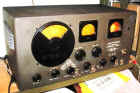
This page is dedicated to the Hallicrafters SX-24 Skyrider Defiant.
The tube line up is 6L6, 76, 80, 6SK7, 6H6, 6K8 and three 6SK7's.
Un-restored this radio received on all bands. The band switch is
touchy, scratchy RF and AF gain controls and the toggle switches take a bit of
time to switch. All this is easily fixed with cleaning and
lubricating. There is an occasional popping and crackle when in
operation. This is most likely caused by a bad capacitor. The S
meter is sluggishly responding and will not zero. This too is probably
because of bad caps and a dirty zero pot. All these radio ailments will be
addressed with a complete and though chassis restoration and bring this radio
back to its proud capacities as a Hallicrafters SX-24 Skyrider Defiant.
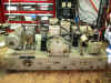
 Original caps and resistors.
 |
 Nice look. Well kept.
 |
 |
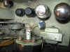
 Chassis could use a cleaning.
 |
 Some work has been done on the S meter and pilot lamps
 |
 |
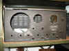
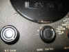 Chipped black paint. Easy to sand and repaint.
 |
 |
 Dial scale cover with index has scratch.
 |
 Black paint needs restored. Black paint needs restored. |
 Mystery Wire. This will be taken care of during the
restoration.
Mystery Wire. This will be taken care of during the
restoration. |
 Naked Chassis.
 |
 S-meter movement protected with a pop (soda) bottle.
 |
 Empty case.
 |
|
|
|
|
Dial scales
Some images are large.
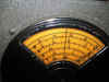
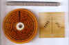 Band spread - Cracked scale and scratched cover.
 |
 Main Tuning in good condition.
 |
 Main Tuning Bezel - scratched.
 |
 Rear of cover - oversized to be riveted to metal bezel.
 |
 Ruler on top of image for sizing.
 |
 S-meter clear cover with mechanical zero is larger to be captured in meter
cover. This cover was replaced with Polycarbonate sheeting.
S-meter clear cover with mechanical zero is larger to be captured in meter
cover. This cover was replaced with Polycarbonate sheeting. |

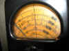
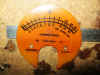 S-meter scale is cracked.
 |
|
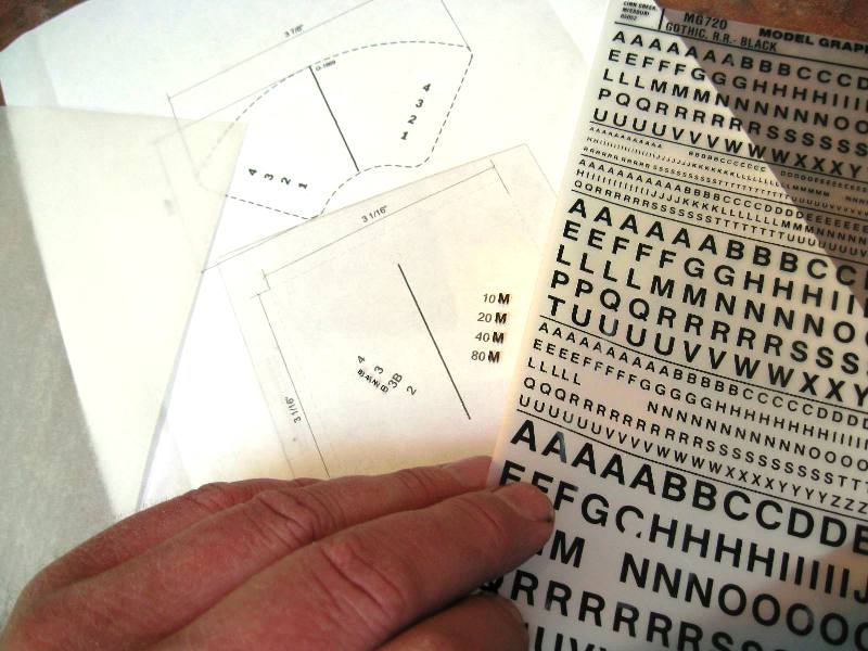
Dry Transfer lettering used on Dial Scale covers
 Get
your materials together. Have a pattern or the original cover. Get
your materials together. Have a pattern or the original cover. |
 I used Black Gothic letters of appropriate size.
 |
 .015 inch thick clear Polycarbonate sheets.
 |
 Cut
out a piece a little bit bigger than your dial scale cover. This is
the Bandspread index. Cut
out a piece a little bit bigger than your dial scale cover. This is
the Bandspread index. |
 Tape
it onto your pattern. Tape
it onto your pattern. |
 Line up the transfer letter over the image and gently rub.
 |
 Four "M"s have been transferred successfully.
 |
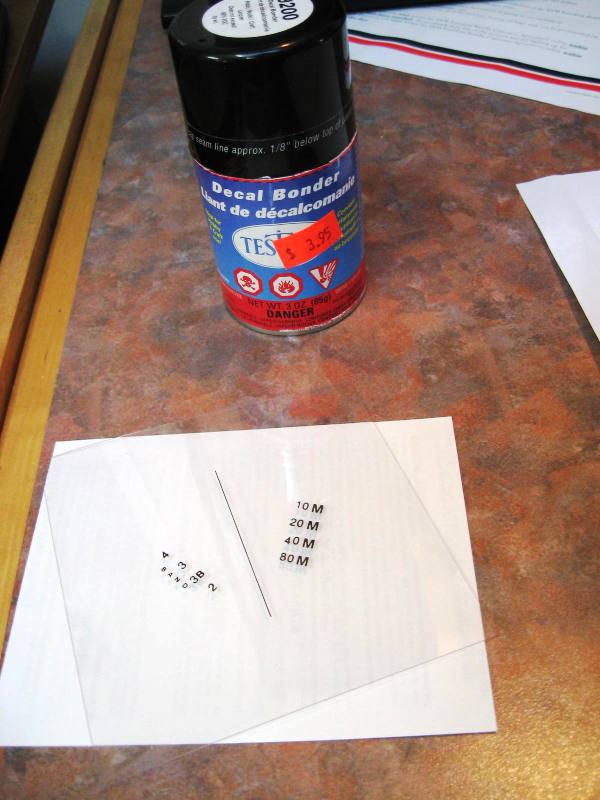
 All lettering has been transferd. I'm pleased.
 |
 Seal down the lettering with Decal Bonder.
 |
Trim the both the polycarbonate sheet and the layout image
to proper size. I repeated this procedure for the main Tuning dial
scale cover. |
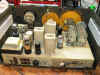
Pictures of the finished cabinet and dial scale cove.
Black bezel (on left) was stripped primed and spray painted. All
dials and meter bezels were cleaned and treated with Magnolia Glayzit.
New Polycarbonate dial scale covers were fabricated and labeled with Dry
Transfer Letters. The letters were protected with Testors Decal
Bonder.
All from "bright" steel was power buffed on a bench
grinder/buffer or with a Dremel power tool and appropriate polishing
compound.
These two pictures do not do the radio justice. The SX-24 looks
much better in person with out an intense flash. |

Side vents were stripped then pained with primer and silver spray
paint. |
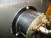
Audio Output Transformer
I have received multiple questions
about replacement audio output transformers for Hallicrafters
radios. I have replaced transformers in Hallicrafters radios (http://www.ppinyot.com/H/sx_71.htm
and http://www.ppinyot.com/sx62a.htm)
where there is a 300 and 3000 ohm output impedance. Both times the owner(s)
did not want to spend $180 plus dollars on a direct replacement. So a
universal Hammond single ended transformer was selected. The up side is
lower cost and the transformer is NEW. The down side is there is no longer
a high impedance speaker connection. But this can be overcome with a
special transformer also by Hammond just for this challenge.
If you must use the original 3000
ohm impedance then a direct replacement, new audio transformer, will be costly
and hard to find. There may be used transformers available from other
sources. If you can live with a standard 4 to 16 ohm output then it is
easy to find a replacement. Here is how I have done it:
Givens:
Hallicrafters SX-24
Output tube: 6F6
Tube output impedance: Class
A, SE output impedance of 7000 (http://www.duncanamps.com/
TDSL)
Pout = 4.5watts
Ia = 38ma (or calculate the max I
through R25 cathode resistor).
Find:
New Output transformers at: http://www.radiodaze.com/hammond15.htm
or other reputable supplier. HX-125BSE to handle the plate current in the
primary and power output.
- If there is physical space (check
the dimensions) get the HX-125CSE. It is less expensive and can
handle more plate current and more wattage. This is the tranny I have
used.
Do:
- Use the 5000 ohm impedance
options.
- Connect black yellow to the
speaker
- Re-label the 300 ohm output to 8
ohms.
- Abandon the 3000 ohm chassis
terminals in place.
- Remove and abandoned C22 (C21
stops parasitic oscillations) and rewire the head phone jack to pick up the
secondary of the new audio transformer, UNLESS I choose to drive a set of
headphones directly from the plate of the output tube with B+ on it.
Personally, I do not want +200 volts, held back by a capacitor (C22), in a head
phone across my skull so this cap and wiring goes bye bye.
- I would parallel the headphone
jack across the secondary or hook it up to interrupt the speaker when the head
phones are plugged in.
- Optionally rework the headphone
jack so it switches in a 150 to 300 ohm 1 to 2 watt resistor in series with the
head phone just to provide some level of attenuation. But I would remember to
cut the volume before plugging in head phones. So I would forget the
resistor.
If there is an original 300 ohm speaker I would then buy and install: http://www.radiodaze.com/hammond12.htm
into the speaker cabinet. This would make the Hallicrafters speaker more
universal to 8 ohm radios. But if the speaker needs reconed just specify 8
ohm voice coil from the reconer. Then use the 8 to 300 ohm transformer if you
put the reconed speaker on a receiver with only a 300 ohm output.
This is how I would do and have done it.

|