
![]()
![]()
![]()
![]()
![]()
![]()
![]()
![]()
|
|
|
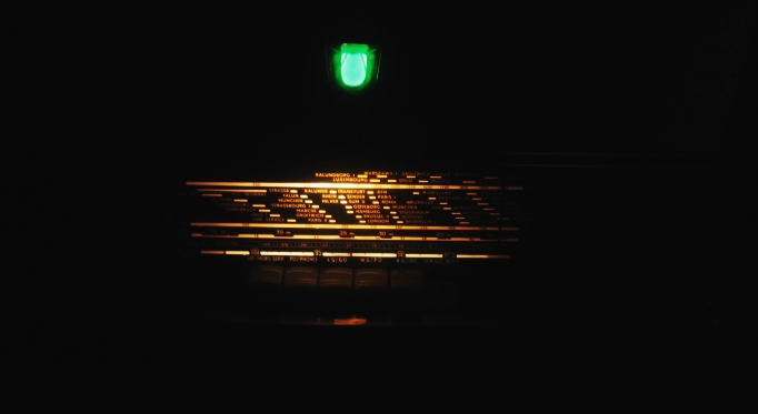
Philips BX553AThis unit in for restoration will have all electrolytic replaced, paper capacitors and carbon resistors. The resistors are of the brown uncoated body type. After passing an initial Dim Bulb tester power up has the radio playing directly to the 120 volt line. The pushbuttons are a bit tentative, all bands received stations or static (no long wire antenna attacked). This is a quick check of all inter-stage, IF, audio and oscillator coil tests. Later alignment may uncover questionable transformers. But this power up test sure beats ohming out each separate transformer and coil.All tubes passed testing with a Heathkit IT-17 emissions tester but two. The EABC80 showed leaks and a dim short lamp glowing on two of three tests. The UL-41 has no tester setting. This tube will be tested in circuit. There is a good discussion of the UL41 propose at: http://www.radiomuseum.org/r/philips_bx553a_bx_553_a.html. Plug this URL into the Google Translate page if you don't read Dutch.
I found a broken IF slug when I started the alignment. Once apart several I unsuccessfully tried two other methods (Epoxy and sticky tape). Super Glue did the trick. It securely held the slug to the screw.
The Bass potentiometer is ineffective. It has a set screw threaded through the shaft. I think this may be made from Unobtainium.
| |||||||||||||||||||||||||||||||||||||||||||||
 |
 |
 A high gloss finish was applied.
 |
 The
finish was wet sanded and sprayed again. The
finish was wet sanded and sprayed again. |
 Until
this mirror like finish was achieved. Until
this mirror like finish was achieved. |
 |
 This is a shot of a switch on the internal AM antenna. The dial is
in the full clockwise position. The tab with red paint throws the
switch to the left. I discovered the external antenna connections
are affected by the position of this switch. Insure it is properly synchronized.
This is a shot of a switch on the internal AM antenna. The dial is
in the full clockwise position. The tab with red paint throws the
switch to the left. I discovered the external antenna connections
are affected by the position of this switch. Insure it is properly synchronized.
To synchronize, turn antenna dial about half way. Take a probe and position the switch tab to the right. The rotating vain will then engage the tab and push it to the left when the dial is fully clockwise. |
|
Contact me including your thoughts and comments. 135,912 unique web site visitors (14,499,000 hits) from October 2004 through August 2011. Copyright © 2004 - 2012. All rights reserved.
|