Frieburg 14


Home Up Saba 125 Frieburg 14 Freudenstadt 125


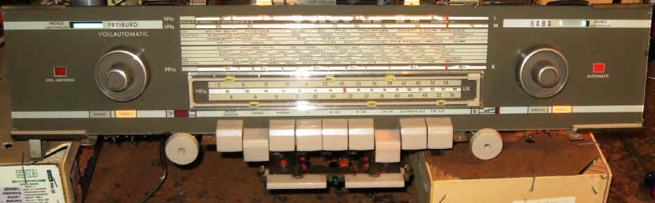
Saba Vollautomatic Freiburg 14 chassis pictures.  


IMG_3941.JPG (164266 bytes)Sparks and burning when the Autotune is on and a new ECC80 installed.

IMG_3942.JPG (116849 bytes)This screw is blocked in and can not be accessed from above.

IMG_3943.JPG (1487325 bytes) Make a tool.IMG_3944.JPG (154771 bytes)

IMG_3945.JPG (113904 bytes)

IMG_3948.JPG (113788 bytes) This fits and turns just enough to break it loose.  I used a dentil pick to unscrew it all the way. 

IMG_3952.JPG (197236 bytes) Free!

IMG_3955.JPG (116833 bytes)There is the source of the arching on that switch made from the compound "Unobtainium".IMG_3962.JPG (99480 bytes)

IMG_3964.JPG (190319 bytes) I believe this is the contact side of the resistor that burned. 

IMG_3966.JPG (192480 bytes)H1 contact is next to the contact that holds the resistor.  The arching contact is connected to C723.

IMG_3967.JPG (201530 bytes)It seems there was 180-240 VAC potiential across the switch H1 and the resistor solder lug (no switch contact) that arched.  And point K goes to the......

IMG_3969.JPG (187901 bytes) ...the grid of Tube 701 triode.  And that explains why this tube tested bad upon arrival.

I will probably have a new bad tube after the grid was "zapped" by ~200 vac and the inductive current from the shaded pole motor.  My solution is to remove the resistor from the switch assemble and use a separate terminal strip. 

IMG_3976.JPG (118263 bytes)Pull apart the switch.

IMG_3980.JPG (206735 bytes) Remove and fill the burned material.  This is mostly cosmetic since I will be moving the resistor off of this solder lug on the switch.  

IMG_3982.JPG (336500 bytes) 

12KV/mm @3mm dielectric strength!!!  And it is so economical and easy to work.  Two part OATAY epoxy sold in the plumbing section.

IMG_3984.JPG (2073122 bytes) Finished and assembled.  That resistor will be relocated.  I believe some good intentioned person sprayed some high cost contact cleaner that left a conductive residue.  And that started the arch.  

Once the insulator was burned the arch had a low resistance path and never stopped until the fuse blew and the ECC80 lost conduction.  

A thank you goes out to Kristen a fellow ham radio operator (well not a fellow but a YL ham known locally as "Zed"), that help me spot the arch.  She just happened to stop in to visit this day! 


This unit has a Stereo Decoder installed.  There were two out of tolerance resistors shown in red on the schematic.  This decoder was also optioned for USA use.  It will receive an alignment along with the rest of the chassis. 

IMG_3927.JPG (1043098 bytes)

IMG_3925.JPG (1061717 bytes)

IMG_3926.JPG (1266540 bytes)

IMG_3929.JPG (1052722 bytes) Replaced parts that were bad and optioned for the US FM reception. 

IMG_3930a.jpg (144715 bytes)Parts in yellow were changed for the USA.

IMG_3930b.jpg (59136 bytes)

IMG_3930c.jpg (86895 bytes) Parts in red were out of tolerance.  Yellow changed for the USA FM broadcast. 


Some other Decoder models and year introduced.   Read this:  http://www.radiomuseum.org/r/saba_stereo_decoder_e16_us16_e.html  Use your favorite translator. 


Chassis pictures with some comments.


IMG_3839.JPG (618493 bytes)This is the chassis as received. IMG_3841.JPG (346685 bytes)There have been part values changed on the Auto tuning circuit (ATC).  IMG_3842.JPG (363695 bytes)This is a power supply for the ATC. IMG_3843.JPG (418002 bytes)Paralled cap on the B+ filter cap. IMG_3844.JPG (358934 bytes) IMG_3845.JPG (477936 bytes)Balance control accessed from behind chassis.
IMG_3847.JPG (349998 bytes)More modifications. IMG_3848.JPG (332577 bytes)This cap us parallel on the Tuning motor.  It's value is for 50Hz line.  IMG_3852.JPG (370736 bytes)Broken wire.   IMG_3856.JPG (391545 bytes)Repaired. IMG_3854.JPG (1067244 bytes) IMG_3857.JPG (421392 bytes) More mods to the ATC
IMG_3860.JPG (408947 bytes)Removed mod. IMG_3861.JPG (401000 bytes)This is the new cap for 60Hz line frequency. IMG_3863.JPG (101973 bytes)More missing insulation.  This is found throughout the chassis.  I thought it was a trouble shooting effort.  The multi colored wires are for the ATC.  IMG_3864.JPG (377916 bytes)This is the 60Hz cap. It turns out Mr. Jingles was dining on the insulation.  He mostly liked the ATC wiring. IMG_3873.JPG (465967 bytes)Selenium bridge repair with 1N4007 diodes.  IMG_3874.JPG (449850 bytes)Drill holes to accommodate the new diodes.
IMG_3876.JPG (241216 bytes)Resealed and marked.  The ink will face the chassis. I added a series resistor. Value determined Hot on the bench with a big wire wound variable resistor.   IMG_3901.JPG (220798 bytes)During alignment I found this AM trap coil.  It has been dined on by Mr. Jingles.  IMG_3902.JPG (308777 bytes)Cement the coil wires to keep them from unraveling further.  IMG_3903.JPG (330426 bytes)Carfully strip the Litz wire and add new leads.  IMG_3905.JPG (326759 bytes) IMG_3906.JPG (238680 bytes)Finished. It has to be glued back in the chassis with 5 minute epoxy. 


Control Transformer V adjustments.

on_chanel.jpg (51382 bytes)

On channel

off_ch.jpg (52940 bytes)

Off channel center

off_ch2.jpg (51252 bytes)

Off channel center other side. 

AGC.jpg (120829 bytes)

This is the AGC voltage from the audio path Ro301-9.  Good and strong.


AGC_cntrl.jpg (122842 bytes)

Control transformer AGC voltage.  This should be 22 volts during alignment.  This is a station reception as displayed on the scope left. 

22 volts can be achieve when 10.7MHz IF signal is injected directly to Ro701-2. breakoutbox.jpg (120641 bytes)

Test socket break-out box.  This makes it real easy to connect to the chassis. 

Proper alignment of Control Transformer V yields 22 volts.  But do not turn the 'Do Not Adjust" screws as some one had in this chassis.  It took many trial and error adjustments to get the proper balance between a strong off channel signal and on channel stability.    balanced_detector.jpg (118038 bytes)

A properly balanced detector.   Cat Nip does NOT yield a stable alignment.


Push Button Lamps

Here is a close replacement for the 8.5 volt 0.15a globular lamp for the Saba Freiburg

I had no success locating the 8.5 volt push button lamps for a Saba Vollautomatic Freiburg 14 radio. I read all the translated comments about the lamps. There was a source 8.5v lamp mentioned. However they did not carry the lamp anymore (unless I did not translate properly). I tried several Midget based lamps and found one acceptable lamp still in production and carried by a vendor for reasonable cost.

The Lamp I used is a Chicago Miniature Co., number 342, 6 volt 0.04 amp 10,000 hour long life T-1 ¾. Mouser Part Number 606-CM34, $1.20 ea., 10 for $10.80. I purchased ten.

The low current rating yields the low lumens output similar to the 8.5 volt globe lamp. It is a close match. And much better than a dark push button.

I have some pictures to show you:

CM342 lamp.JPG (148322 bytes)


comp_342_85v.JPG (137636 bytes) 342_button.JPG (138682 bytes)

New 342 6v 0.04a lamp

8_5v_button.JPG (133369 bytes)

Original 8.5 volt

dial scale crop1.JPG (670246 bytes)

Button lamp compared to dial scale lamps (Stereo and Music)

An alternative it to use a different 6 volt midget base lamp or a "Grain of Wheat/Rice" lamp and a current limiting device (resistor, diode, etc) to adjust the intensity. I found using 342 lamps to be much simpler, did not modify the circuit architecture or add additional points of failure.

I changed all the button lamps so the intensities match. It looks good. But I do not have a completed radio picture. The owner shipped only the chassis. And it does have an undamaged dial glass. And you can bet I shipped the glass back in a separate wood box and not on the chassis.

If you find viable lamp alternatives, some lamps and current limiting solutions to be considered and tested please mention them.

Hit Counter

 Contact me including your thoughts and comments. 

Please see the LINKS page.  I have collected many resources over the years.

135,912 unique web site visitors (14,499,000 hits) from October 2004 through August 2011.

Copyright © 2004 - 2012. All rights reserved.