Saba 125


Home Up Saba 125 Frieburg 14 Freudenstadt 125


SABA Phono Super 125 
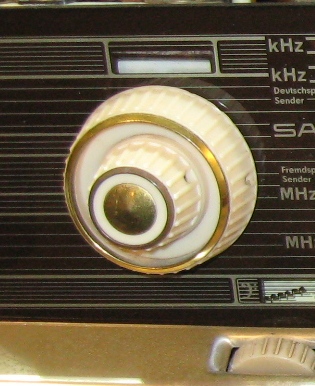
IMG_3033.JPG (1028820 bytes) IMG_3035.JPG (929597 bytes)Push the tone arm to the right to start the platter motor. IMG_3037.JPG (718169 bytes)This crystal cartridge has low output. It has been replaced.  The 33-45 needle was worn out.  The tone arm skated across the records.  But not with a new needle. IMG_3036.JPG (890182 bytes) IMG_3309.JPG (366324 bytes)The motor switch-off cam needed adjusted.  The motor shuts off at the end of record. 

I used two fruit crates as a work support. The power computer speaker was a convenient monitor. 

IMG_3040.JPG (1106412 bytes) IMG_3043.JPG (1197670 bytes) IMG_3039.JPG (1196548 bytes) IMG_3314.JPG (255229 bytes) IMG_3315.JPG (237186 bytes)Replacement tuning indicator.
IMG_3317.JPG (345775 bytes)Selenium bypassed with a silicon diode and 68 ohm resistor.   IMG_3318.JPG (510572 bytes)Restored underside.  IMG_3316.JPG (298583 bytes)Tone control was split.  I used plastic weld and reinforced with epoxy.  IMG_3320.JPG (330801 bytes)This is how the knob looks from behind.  You can not see the epoxy from the front.   


SABA Villigen 125 


This unit was not as lucky as the one above.  It must have took a hit or drop in shipping.  The front panel metal chassis bent, flexing the glass.  And glass does not flex so it broke.  I hope to find a replacement or reproduction from a European resource.  (See the Vendors under the Links page and the Dial Scale page).  

IMG_3052.JPG (1010575 bytes) IMG_3026.JPG (1156996 bytes) IMG_3030.JPG (982552 bytes) IMG_3031.JPG (1107246 bytes) IMG_3047.JPG (1178121 bytes) IMG_3048.JPG (1050029 bytes)
IMG_3050.JPG (1182820 bytes) IMG_3025.JPG (1048616 bytes)        

Seen here on Radiomuseum.org


The dial scale has arrived.  It was great luck to find one.

IMG_3226 b.jpg (128261 bytes)

IMG_3227 b.jpg (114740 bytes)  

Skalenscheiben und  Rückwand Forum

This site has used dial scales. 


The restoration begins


IMG_3231.JPG (366872 bytes) IMG_3232.JPG (226209 bytes) IMG_3245.JPG (315046 bytes)

IMG_3234.JPG (265743 bytes)

IMG_3238.JPG (319302 bytes) After forming little by little the chassis is straight.  The replacement glass fits with out interference. IMG_3243.JPG (329170 bytes)  IMG_3248.JPG (735549 bytes)
IMG_3246.JPG (940213 bytes) IMG_3247.JPG (503339 bytes) IMG_3249.JPG (368553 bytes) IMG_3251.JPG (281169 bytes)This cap has a shield and ground wire. IMG_3252.JPG (133505 bytes)Wrap the aluminum duct tape around the new cap and ground wire.  IMG_3254.JPG (115245 bytes)Make sure the ground wire contacts the bare metal shield. 

IMG_3255.JPG (102891 bytes)I don't know if it is important but I made up the capacitance from the Capacitor to ground shield with a parallel cap. 

IMG_3258.JPG (321792 bytes) Heat is  shrink used to hold the work together and provide electrical insulation.  IMG_3260.JPG (203325 bytes)

Label on the FM tuner.

IMG_3262.JPG (318424 bytes)

Checking for caps and resistors inside the tuner. 

IMG_3263.JPG (190754 bytes)

B+ measured ~176v

IMG_3265.JPG (226979 bytes)

Things got a little hot in this selenium rectifier!

IMG_3266.JPG (286968 bytes)This looked like a good idea.  But there is not enough room in the case.  The resistor has to be mounted external to the case.  IMG_3268.JPG (120158 bytes)

1N4007

IMG_3272.JPG (180200 bytes)Make two top painted lamps.  The original has red glipt on it.  IMG_3274.JPG (83620 bytes)This burnt cathode resistor foreshadows  a bad output tube.  It tests good in a tester but hums and draws high current in the chassis.  IMG_3230a.JPG (78159 bytes)

Before brass cleaning

IMG_3275.JPG (410055 bytes) 

Restored.

IMG_3282.JPG (465261 bytes)

This looks nice with the replacement dial glass.

IMG_3286.JPG (204195 bytes) 

Brasso to the rescue.

IMG_3287.JPG (217707 bytes) IMG_3288.JPG (199901 bytes)  


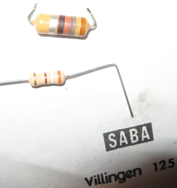
The original ECL82 (6BM8) has a short.  A new tube performs well with out hum and pulling the B+ down. I put a series resistor in line with the diode.  I selected the resistance by trial and error measurement.  I set the line voltage selector to 125v by measuring the filament supply. 

Click here for schematic.


Packing

I did not want to take a chance at the replacement dial glass getting broken again so I built a wooden crate.


IMG_3289.JPG (956621 bytes)This wooden box should protect the dial glass.   IMG_3290.JPG (1007101 bytes)The joints are glued.  IMG_3291.JPG (957244 bytes)Bubble wrap used to keep anything that comes loose from bouncing around. 
IMG_3293.JPG (990831 bytes)The top is NOT glued.  IMG_3292.JPG (1061766 bytes)Four bottom screws secure the chassis to the box.  IMG_3294.JPG (963845 bytes)The box is wrapped in three inches of bubble wrap.  This should absorb any shock and allow for deceleration and decreased shock to the chassis and dial glass. But as you know this is no guarantee of a safe delivery.  The speakers have also been wrapped and set parallel to the box.  A fresh new double wall heavy duty box was used. 


Hit Counter


 Contact me including your thoughts and comments. 

Please see the LINKS page.  I have collected many resources over the years.

135,912 unique web site visitors (14,499,000 hits) from October 2004 through August 2011.

Copyright © 2004 - 2012. All rights reserved.