|
|
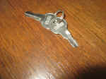
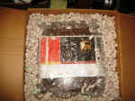
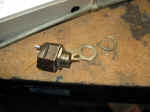
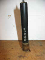
Found keys inside cabinet. |
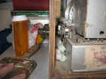
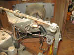
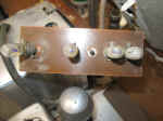
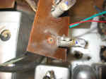
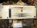
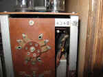
Side controls.
Band switch and a unique variable capacitor tone control. |
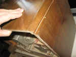
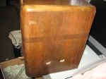
Split. This should glue up and disappear. It did. |
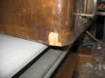
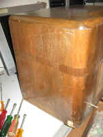
Chipped veneer. The shipping box has a dented corner. It
may have been dropped. |
 |
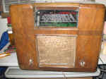
There is no dial scale cover present. To be investigated. |
 |
 |
 |
 |
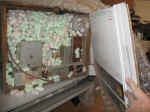
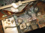
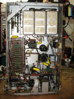
Very clean inside bottom of chassis. |
Note to self, re-tension this cable. |
 |
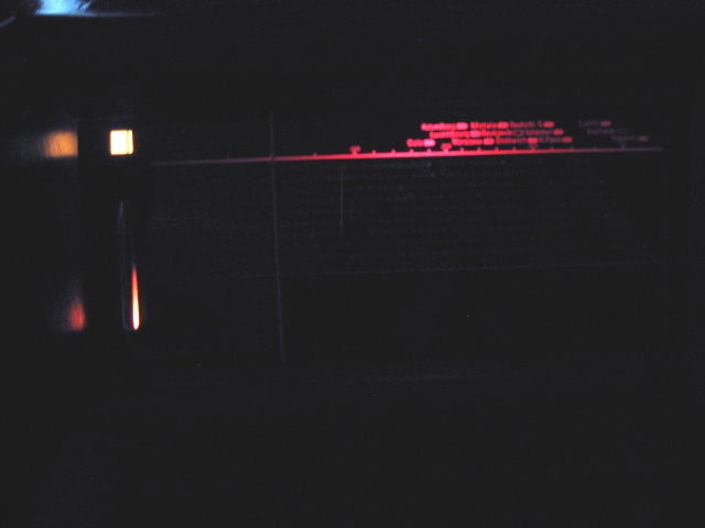
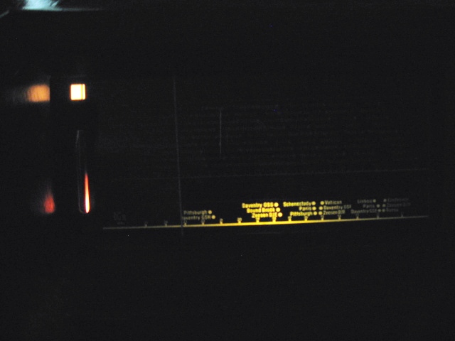
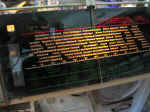
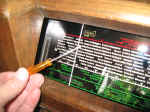
Dial scale in good condition. |
 |
 |
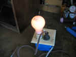
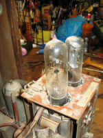
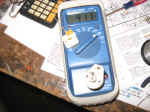
Dim Bulb test ok. |
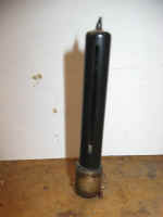
Ballast tube on left. |
 |
Sticky power switch. |
Removed, flushed, cleaned and lubricated power switch. It works
great now.
|
Original cathode bypass cap on top.
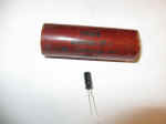
Replacement cap on bottom.
Same capacitance higher working voltage.
|
Restoration has begun.
|
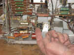
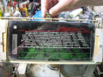
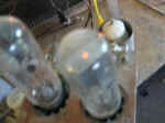
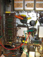
Look close you can see the reed
contacts. Those will be tough to clean. 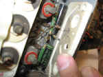
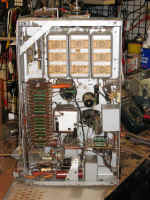
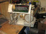
I have removed the three shields shown at the top of the picture to the
left.
|
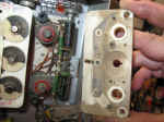
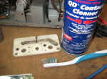
These cans shield the coils and reed switches for the band
selectors. A good cleaning will help the operation and alignment of
this radio.
|
There is lots of dirt that needs to be cleaned and two capacitors at
least in the first RF can.
|
The two caps are on the top. I do not believe there are other
needing replaced under the other shields.
|
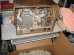
It is a surprise to me how robust this
radios is. It easily falls into the "Boat Anchor" category.
It must have cost the initial owner a real bundle. Perhaps near a
blue collar years wages.
|
Neon tuning indicator
|
It still works!
|
 |
 |
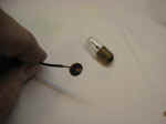
Broken lamp holder of the LW band.
|
 |
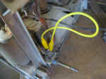
Soldered a wire from the inside contact center conductor to....
|
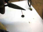
..the rivet of the lamp mount.
|
The new wire is soldered to the original rivet and the lamp now works
|
 |
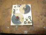
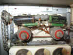
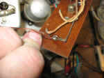
The top capacitor is bad. It is used to set the 600 kHz oscillator.
IN the US it is referred to as a "padder".
|
The square adjustable cap is used during alignment of the 600khz
oscillator. The round capacitor below along with a parallel fixed
capacitor was permanently installed.
|
Finished and aligned chassis.
|
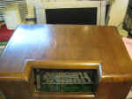
No cover glass. But after staring at the inside of the cabinet
opening and looking....
|
...at the chassis dial scale it occurred to me. There is enough
space under the dial glass retainer brackets to accommodate a glass
cover.
|
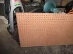
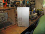
This perforated board is to be used as a replacement back.
|
Remove and replace old speaker isolation gasket material.
|
 I
also replace many other rubber grommets and washers that are hard as
rocks. I
also replace many other rubber grommets and washers that are hard as
rocks. |
 There is a speaker on-off switch. That has been
bypassed and can be reconnected. This shuts off the internal speaker
if you have the external speaker.
There is a speaker on-off switch. That has been
bypassed and can be reconnected. This shuts off the internal speaker
if you have the external speaker.
A special high impedance speaker "system" and
transformer is needed.
DO NOT plug in a regular speaker!!! |
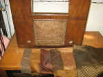
Time to choose... |
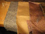
..a new grill cloth. |
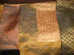
Click on picture to enlarge. |
Choose from left to right the position number, 1 to 6. |
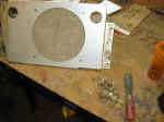
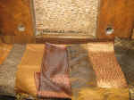
The speaker cloth has been mounted to a board. This is so...
|
..it may be easily removed for future wood restoration work.
|
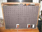
A new back cover.
|
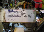
This may be a serial number.
|
*On final testing the
"Hot chassis" engineering design showed up. The original
engineering of this unit connects one wire of the line cord to the metal
chassis as a return ground. This was common and accepted practice when this
radio was made but would never be approved today. This means that depending
on how the plug is inserted into the wall outlet and how the wall outlet
is wired, one way there is little to no voltage on the metal chassis,
screws and any metal protuberance. The other way you plug the radio
in put the full line voltage on the all metal points of this radio and
anything like a phono plugged into it. This is clearly visible on
the schematic
diagram. |
|
I just need to wrap and box this heavy
radio up for shipping. It was damaged getting here and the wood is
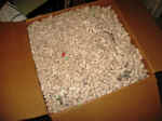
very dry. I will be adding more padding and a bigger
box. |
http://www.radiomuseum.org/r/korting_supra_sel37_sb4346gw.html
I will use these docs to verify the model number.
*There are three options to a Hot
Chassis radio that I can speak of:
1) Use the radio as designed
and be aware of the Hot Chassis attributes and short comings.
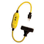
2) Use a Ground Fault Circuit Interrupter
(GFCI) wall outlet or accessory to add protection.
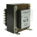
3) Use an External or internal
Isolation Transformer.
I use an external B&K isolation
transformer specifically tailored to bench service. That is, it has
selectable voltages. Selectable voltages are not needed for normal
isolation use.