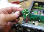
This suspected jack was cleaned with De-Oxit and resoldered.
|
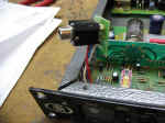
|
|
|
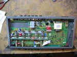
|

The new input jack
|

Wired and installed.
IMPORTANT NOTE. Use a
short cover screw. The original shorted to the phone jack solder
tab.
|

New Output jacks insulated with ACE Hardware fiber washers and O ring
(not seen) to center the connector in the panel hole.
|

New output jacks wired in with high temperature & voltage stranded
Teflon coated wire.
|
These are Switchcraft Silver plated commercial grade
jacks. The input jack is number 502-14B 3 conductor 1/4"
phone. The output are 502-11, two conductor phone. Don't forget the
insulating washers for the output connectors.
|

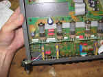
Board interconnections resoldered.
|

Any high stress joint was resoldered.
|

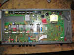
I am listening to this pre-amp as I update this page. I have an
FM radio as the input source and amplified computer speaker as the output.
Not the best acoustic response but good enough for a long hard burn-in!
|
|
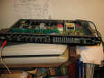
All other controls and the rear AC power receptacle have been cleaned
and lubed with De-Oxit.
|
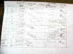
Tube test results. The 2nd to last column is the the Cathode
activity test with a reduced heater voltage.
The last column is the minimum GM to be good.
All tubes passed.
|
|
|
|
