B600


Home Up 7G605 Bomber 7G605 Clipper 8G00TZ1 B600 T600 Brown T600 Battery 50A1/1L6 AM Broadcast Croc covering G 500 Exterior


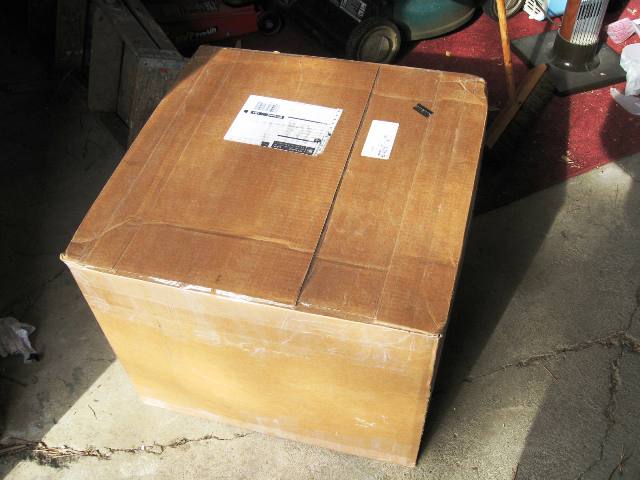
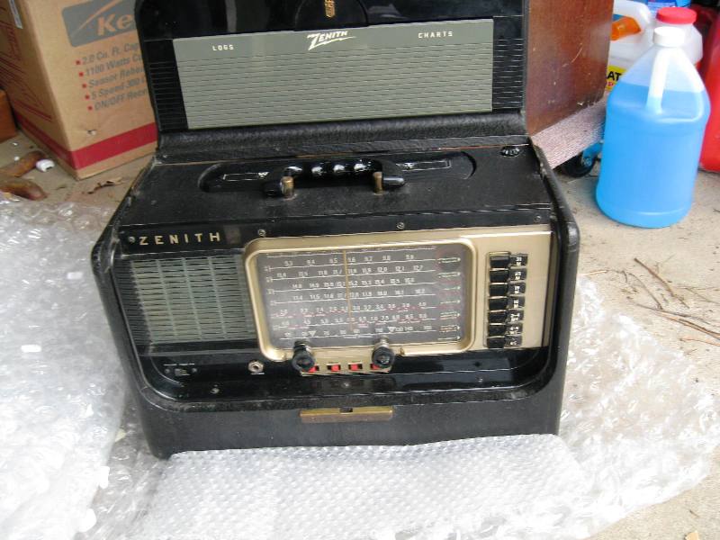
This is my B600 I have in the shop.  This was my first vintage radio that got me started with the Vintage radio obsession.


IMG_3918.JPG (707885 bytes) IMG_3919.JPG (775169 bytes) IMG_3920.JPG (931172 bytes) IMG_3921.JPG (388077 bytes)

This chassis has been totally restored.  There is currently a solid stage 1L6 and solid state 50A1 tube inside.  I keep the original operational vacuum tubes separate and run this unit with the solid state tube versions.

I have cleaned the cabinet and kept its original vintage look.  The only faults with the cabinet are the hair line cracks between the tone switches.


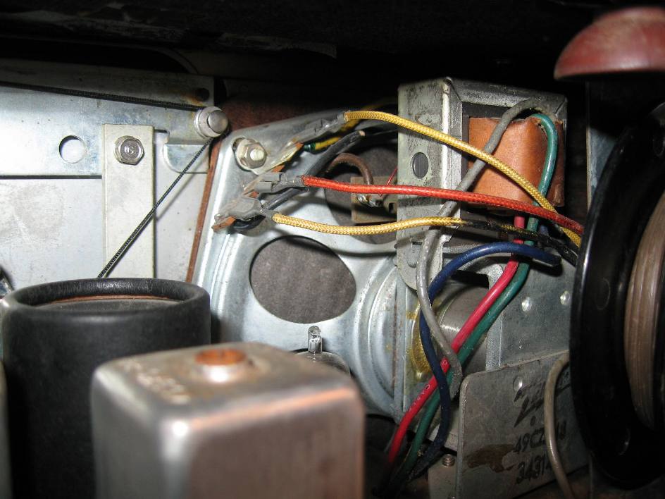
The B600 is a six tube radio that includes miniature tubes, the venerable 1L6 and 50A1 ballast tube.  This radio was DOA.  It played once the chassis was removed, the substitute ballast tube pins straightened and replaced and the phones jack was jumped with an alligator clip test lead.  The Head phone jack needs attention with Emory cloth and contact cleaner or replaced.


img_0134.jpg (45836 bytes) Box undamaged img_0135.jpg (60823 bytes) img_0136.jpg (66250 bytes)Doubled Boxed img_0137.jpg (51886 bytes) img_0138.jpg (52272 bytes)
img_0139.jpg (50259 bytes)Lots of bubble wrap img_0140.jpg (83626 bytes) img_0141.jpg (102741 bytes)This is a good idea.  The log latch is bent and held the grey pull down from recessing in the stowed position. img_0142.jpg (75934 bytes) img_0143.jpg (99942 bytes)
img_0144.jpg (62372 bytes) img_0145.jpg (78929 bytes) This is the bent log pull down img_0146.jpg (54486 bytes) img_0147.jpg (37357 bytes) After straightening. img_0148.jpg (49096 bytes)It works now.
img_0149.jpg (106248 bytes) Log latch in stowed position. img_0150.jpg (105405 bytes) The substitute 50A1 was loose in the chassis. img_0151.jpg (88716 bytes)Bent copper pins.   img_0152.jpg (74370 bytes)Pins straightened and substitute 50A1 replaced. All voltages will be checked to insure this substitute will not adversely affect the circuit. img_0153.jpg (81729 bytes)Missing pin on weaved antenna wire.  Does not affect performance. 
img_0155.jpg (84830 bytes) Unit did not play with chassis in cabinet. Head Phones wires attachment point to speaker.   img_0156.jpg (129470 bytes) This cable will be repositioned. img_0157.jpg (327249 bytes) The selenium diode was replaced with more modern diode.  This too will be replaced by a 1n4007and a dropping resistor.  img_0158.jpg (270542 bytes) Top side. img_0159.jpg (146527 bytes)Stress cracks from tight screws and no washers.  


IMG_0166.JPG (248589 bytes) Model Number   IMG_0165.JPG (359858 bytes) IMG_0164.JPG (267443 bytes) Sticker IMG_0162.JPG (211324 bytes) Serial Number
IMG_0163.JPG (207958 bytes) Chassis Number IMG_0161.JPG (174380 bytes) Prepare to cut off Electrolytic Cap (black can) IMG_0160.JPG (203961 bytes) Replacement Electrolytic B600.jpg (115260 bytes) Under-chassis progress to date.  Components are about 1/2 way completely replaced. 
IMG_0169.JPG (246417 bytes) With out annotations.      


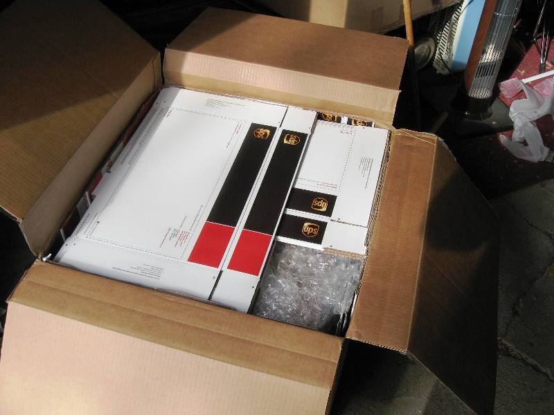
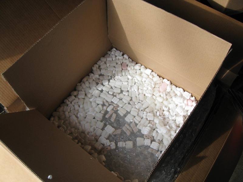
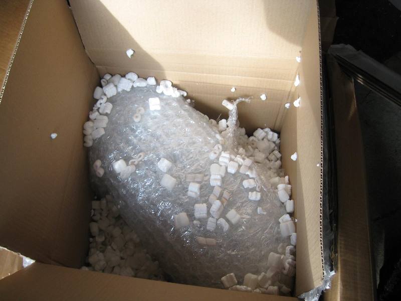
Final set of pictures.  

IMG_0173.JPG (330665 bytes) Completed component change out.

The volume control was bad and needed replaced.  

IMG_0174.JPG (333955 bytes)Bezel pulled for cleaning.  IMG_0175.JPG (297924 bytes) Front bezel and plastic parts treated with Glayzit inside and out. IMG_0177.JPG (288138 bytes)  As Shipped.  IMG_0178.JPG (349992 bytes) As Received.  Exterior not treated. 


There are a few decisions to be made about this radio. The concerns are:

  1. The Dial scale has cracks.  Should it be replaced?

  2. There are no knob "Brights" (shiny metal disks on the two knobs). Should new brights or knobs be acquired?

  3. The Wave rod retainer latch is missing.  Fabricate a new retainer or find a used Wave Rod cap with retainer.

  4. There is a substitute for the 50A1 that does not regulate the current in the filament string.  Replace?

  5. The 1L6 tests good in the tube tester but fails to oscillate on the high bands when the line voltage is at 111 vac and fails to oscillate on Battery when the A supply drops to 8.5 volts DC.  Sold it be replaced or depend on the U.S. line voltage regulation and fresh batteries?


Oscillator Drop out

Band  Line Voltage vac  (Specified is 117vac)
18.0 MHz  16 meters 111
15.6 MHz  19 meters 110
12.2 MHz  25 meters 109
Broad Cast  540 - 1600  KHz  103

This radio is alleged to function down to 90 vac line voltage according to the service literature.  (Note - The service Literature does not specify if all bands are to work at 90vac line voltage.)  This explanation is located with the alignment table as found on: http://www.transoceanic.nostalgiaair.org/600/B600.pdf

The 50A1 Iron wire ballast tube is supposed to regulate the filament string current to 56ma +- 5ma.  This tube has been substituted by what I can determine to be a fixed power resistor in a plastic tube.  Restoring the 50A1 may rectify the drop out at less than US specified line voltage. And protect the 1L6 during over voltage conditions.

The 1L6 was replaced with a New Old Stock never used tube and the Oscillator dropped out at around 98 vac.  My concern would be the over-current condition the substitute 50A1 allows in such an expensive tube to replace.  It would be foolish to replace the 1L6 with out using a new 50A1 or a suitable Solid State current regulator.  

One could legitimately argue the 50A1 is no longer needed in the U.S. with the quality of line voltage.   Other models of the Transoceanic using the 1L6 does away with the 50A1.  A power resistor replaces it.  Personally I would use a Solid State current regulator.  They last much longer than the 50A1s.  It is not a matter if the 50A1 will burn out but when. 


Decision Table

Item Cost Substitute
50A1 $34 +shipping $22.50 - $.33.65 Solid State delivered.
1L6 $56 subject to supply/demand +shipping  Not today, it is $73.50 About $56. Solid State delivered.
Volume control  $11.25 NA
Knob Brights $10 - $20 guestimate.  NA
Plastic Dial Scale ??  To be found. NA


Restoration has been completed.  

The cosmetics have been addressed.  The leatherette cleaned and stained with black leather dye and preservatives, new brights applied to the knobs, replacement plastic dial scale (with markings), brass shined up and plastic treated with Novus #1 plastic polish. 

The chassis performance is unchallenged.  A NOS 1L6, a NOS D5TF30 (50A1) (in place of some fixed resistive substitute), full chassis restoration (caps and resistors), voltage dropping resistors compensated for a new 1N4007 diode, mechanical cleaning, new volume control, check on a battery pack, checked on a varriac down to 71vac and a complete alignment to burn-in to final alignment.  It receives well on all bands.  

See detailed performance results with a new D5TF30 (50A1) and 1L6 in this chassis here: http://www.ppinyot.com/50a1.htm  I am particular about performance.  

IMG_0209.JPG (257753 bytes)  IMG_0216.JPG (319141 bytes) IMG_0219.JPG (438853 bytes)  IMG_0221.JPG (184609 bytes) Original dial scale.   IMG_0212.JPG (287071 bytes)   IMG_0213.JPG (297917 bytes)  IMG_0211.JPG (299318 bytes) New dial scale. IMG_0214.JPG (265058 bytes)  IMG_0215.JPG (283139 bytes)
IMG_0217.JPG (278718 bytes)  IMG_0218.JPG (240539 bytes) IMG_0210.JPG (239369 bytes) This packing material is to be removed before powering up. The cord spool must be removed and packing material removed from on top of the very hot 50A1 ballast tube. The packing material protects the tubes should one come out of its socket. 


Happy Restorations!                                                                                                                                                             Hit Counter


 Contact me including your thoughts and comments. 

Please see the LINKS page.  I have collected many resources over the years.

135,912 unique web site visitors (14,499,000 hits) from October 2004 through August 2011.

Copyright © 2004 - 2012. All rights reserved.