Model 8G00TZ1
Filament Dropping Resistors.
This Zenith Transoceanic model 8G00TZ1 uses a miniature half wave rectifier
for AC operation. The operating voltage of this radio (for bench testing)
is specified at 117vac. Replacement of the filament voltage dropping
resistors are critical to maintain good B+ and sensitive operation.
It should be noted the Sam's specified replacement resistor is 1000
ohms, However, a note at the bottom of the table instructs the
technician to set the resistance at the original 970 ohms. This is
critical to maintaining good B+ for different line voltages.
 The power resistors are
epoxies to the chassis for improved heat
dissipation. The original resistor (R19/20 Riders, R78
Sam's) is used as a terminal/mounting strip. The power resistors are
epoxies to the chassis for improved heat
dissipation. The original resistor (R19/20 Riders, R78
Sam's) is used as a terminal/mounting strip.
Model 8G005TZ1, chassis 8C40TZ2 with 117Z3 half wave
rectifier miniature tube.
|
|
 click this.
Most critical to proper B+ is R80 (or R18 on Rider's), 56 ohm (Green, Blue, Black). A
higher value put the B+ out of range.
|
For
Model 8G005YT with the 8C40 chassis - Calculations for R18 - 20
(Rider's) filament dropping resistors for the 8C40 chassis that use a
117Z6 octal tube.

The calculations for the 970 ohm "candohm" resistor
applies to other chassis as well (i.e., 8C40TZ2).
|

|
Replaced filament resistors in a 8C40 chassis using a 117Z6 full wave
octal rectifier tube. The first 1K ohm resistor measured 983
ohms. Therefore, no parallel resistor was added.
|
Once the filament resistors were replaced (R78 a & b and R80 8C40ZT2
chassis) the line
voltage was varied while monitoring B+. The radio functioned well on the
SW bands over a wide range of Line voltages. With R80 too high (a commonly
available resistance) the oscillator failed on lower line voltages.
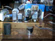
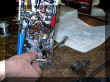
 This is the Chassis just removed from the radio
case. This is the Chassis just removed from the radio
case.
|
|
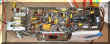
 This is the restored chassis with all bad
capacitors and resistors replaced. This is the restored chassis with all bad
capacitors and resistors replaced.
|
Electrolytic "Can" capacitors.
All Wax/paper capacitors are routinely replaced. Electrolytic
capacitors are cut open, gutted and refilled with modern equivalent
capacitors. The covers are secured back on to the electrolytic to maintain
the original look.
See the Capacitor Page for detailed examples of on the 8C40 chassis capacitor
restuffing.
UL Safety Rated Capacitors.
It should be noted there is a 0.05 uf capacitor (C13 chassis 8C40, Riders)
connecting chassis ground to B- (circuit ground) that if shorted would
present one side of the power cord to the chassis. Therefore, when
performing a restoration, it is recommended this
capacitor should be replaced with the UL Safety rated type. C29 in the same
chassis is directly across the power cord. It is also recommended that
this capacitor be replaced with the UL
safety type. See http://www.justradios.com/safetytips.html
for information regarding UL safety capacitors. Watch for this condition
where a capacitor is connected across circuit ground to chassis in other
radios.
UL rated safety Capacitors installed in the 8C40 chassis for
C13 and C29.
|

|

|
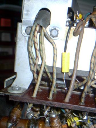
Parts placement.
It is important to maintain the relative
position of all replacement components to the originals. Alignment
is affected by the components proximity to each other.
The yellow capacitor below the detector coil (right) was particularly
sensitive to placement under the coil for proper alignment. When the
capacitor was against the chassis as was the much larger original, one of
the SW bands was extremely weak. Once moved the test signal came in
loud and clear.
|

|
To help maintain the components original position, the original part was
clipped away as close to the body of the component as possible. Two hooks
were formed on the remaining lead wires. The new component was formed with
two opposing hooks and soldered into place. Position insensitive parts
(i.e., in the power supply section) were replaced by de-soldering the whole original
component.
Alignment considerations.
During alignment of the Broadcast Band, the oscillator
adjustment at 1600k Hz, oscillator trimmer had to be opened up almost 0.25
inches with no adjustment range remaining (too far for my
liking). It should be closer. About 2 to 3 mm.
Moving the lead wires that connect the trimmer
(C19, ch 8C40) to the oscillator coil
help considerably. The wires shown on the right were grouped
together. Experimentation with a plastic stick determined the green
striped wire (connected from the trimmer to the oscillator coil) had the
greatest effect. Once separated, the trimmer capacitor could
be closed down thus yielding more adjustment range. Attempting the
same technique for the detector coil trimmer (C12) adjustment yielded no additional
benefit.
All antenna trimmer capacitors were aligned once the chassis
was reinstalled into the restored case.
|
 |
Here are some additional pictures during a G500 restoration.
 Capacitors in place of the old foil can cap.
|
 Better look.
|
 Hot melt the cardboard cap.
|
 Push on until hard.
|
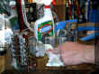 Cleaning the dirt off of the chassis.
|
 Removing
the worn speaker grommet Removing
the worn speaker grommet
|
 Had to cut it off.
|
 Replacement Grommets
|
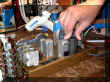
 Grinding rivets on old power resistor.
|
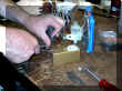
 Removal of the old power resistor. It will go bad soon. So
better to replace it now while on the bench.
Removal of the old power resistor. It will go bad soon. So
better to replace it now while on the bench.
|
 Completed under chassis. New power resistors are Epoxy(ed) to
chassis. this adds mechanical strength and good heat conduction.
Completed under chassis. New power resistors are Epoxy(ed) to
chassis. this adds mechanical strength and good heat conduction.
|
|
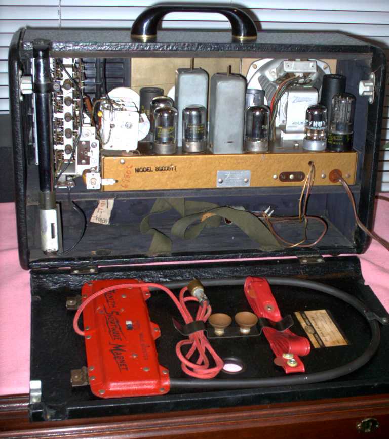
Exterior
Below are three photos of the completed 8G005YT, chassis 8G40 Transoceanic.
 The
case was disassembled, surface mounted hardware removed and all parts
cleaned. The
case was disassembled, surface mounted hardware removed and all parts
cleaned.
|
|
 All of the brass was shined up with Brasso and a coat of Minwax Finishing
Past Wax. A replacement clear plastic dial cover was installed in
place of the missing one. Non brass metals were treated with Tarn-X.
All of the brass was shined up with Brasso and a coat of Minwax Finishing
Past Wax. A replacement clear plastic dial cover was installed in
place of the missing one. Non brass metals were treated with Tarn-X.
|
|
 The completed and aligned chassis displays all the new capacitors,
resistors, UL safety capacitors and two additional line fuses. The
can capacitors present on the top of the chassis have been "re-stuffed".
The completed and aligned chassis displays all the new capacitors,
resistors, UL safety capacitors and two additional line fuses. The
can capacitors present on the top of the chassis have been "re-stuffed".
|
 Additionally; The black case was treated with Kiwi Black
Leather dye, a coat of Kiwi Liquid wax and a buffing.
The plastic bezel was treated with Glazit. Additionally; The black case was treated with Kiwi Black
Leather dye, a coat of Kiwi Liquid wax and a buffing.
The plastic bezel was treated with Glazit.
|
|

Battery page with general TO links.
|
|
Thank you!

Please email  any
comments or questions. any
comments or questions.
|
Transoceanic History
Try this detailed story at http://www.radiomuseum.org/forum/zenith_trans_oceanics.html.
You may need to register. For a time it was free registration for US
participants. I am not sure how long this is being offered. On a
side note, from what I have gathered the charge/fee is to keep the riff-raff off
of their well maintained and informative forum. I frequent there.

|