 x is the grid spacing in the x-direction. To compute the gradient vector, you use similar equations for the y and z components of the gradient, and then normalize the gradient to unit length. This unit vector can be used for Gouraud shading.
The authors are scientists at GE's R&D labs. They can be contacted at schroeder@ crd.geo.com.
The power of computer graphics to create new worlds and to excite and inspire us is undeniable. Movies such as Jurassic Park and 3-D computer games like Myst and DOOM are examples of the power of graphics. But computer graphics have many other practical and useful capabilities. The ability to visualize complex systems and data is one example.
Visualization is a relatively new field first described in the 1987 NSF report, "Visualization in Scientific Computing" (see "Visualization in Scientific Computing," B.H. McCormick, T.A. DeFanti, M.D. Brown, Computer Graphics 21(6), 1987). This report, which described fundamental computational challenges, named scientific visualization as a key technology for digesting the massive amounts of data generated from computer simulation and data acquisition. Since then, the terms "data visualization" and "information visualization" have also been frequently used. Data visualization encompasses scientific visualization as well as the application of visualization to nonscientific fields, such as finance and business. Information visualization deals with data that have little or no organizing "structure"-marketing demographics, the contents of a text document, or information on the World Wide Web.
Whatever name we use to describe the field, the essence of visualization is transforming complex information into visual form. The purpose of this approach is to engage the human visual and perception systems. Visualization is, arguably, the most effective way to communicate and describe complex and voluminous data.
In this article, we'll focus the powerful yet simple contouring algorithms employed by visualization practitioners. Contouring is used to visualize scalar data-single-valued data located at discrete points in space.
If you've ever looked at a weather map, you've seen examples of contour lines. Each contour line represents a region of constant scalar value, whether the scalar is atmospheric pressure (isobars), temperature (isotherms), or rainfall. These contours are also referred to as "iso-contours." The process of constructing iso-contours is called "contouring."
To construct 2-D contour lines, assume that you have a series of scalar values defined on a grid of uniform, square cells; see Figure 1. Choose a fixed value, called the "iso-value" or "contour value" (here value=5.0), and find a cell edge with end points that have scalar values both above and below the contour value. Using linear interpolation, compute the point X that is on the contour. Once you have found this seed point, begin tracking the contour line (starting at point X) as it enters and exits each cell in the grid. Eventually, the contour will close in on itself (forming a closed loop), or the contour will exit through the boundary of the grid.
Another approach to 2-D contouring is the marching squares technique. (We are introducing this algorithm in preparation for the 3-D marching cubes algorithm.) Marching squares tackles the contour problem one cell at a time. Cells either contain pieces of the contour or are empty. To find the nonempty cells, look for cells that have edges straddling the contour value. You can characterize each cell by looking at whether a vertex scalar value is above or below the contour value. Since there are four vertices in each cell and two possible states for each vertex (above or below), there are 24 = 16 cell cases. Figure 2 depicts these 16 cases. These cases only tell you how the contour line intersects the cell, not the location of the intersection.
With this observation, you can construct a simple contouring algorithm. For each cell in the grid, you generate a 4-bit index by performing successive logical OR operations with an initially zero index (see Example 1, where CASE_MASK[]= {1,2,4,8}). This creates an index into the table of Figure 2, which tells you directly the topology of the contour segment, which edges of the cell are intersected by the contour, and which vertices to use for interpolating the intersection points. The interpolation is the same linear interpolation used in Figure 1. Once you have traversed all the cells in the grid, all the resulting line segments form the contour. If desired, the coincident vertices generated in neighboring squares can then be merged to form a single contour line.
One important detail to note is that some of the cases (cases 5 and 10, for instance) are ambiguous; that is, there is more than one way to generate contour lines in the square. You solve this problem by simply choosing one of the two possibilities.
While creating contours in 2-D is relatively straightforward, creating contours in 3-D is more complex. In 3-D, the contours consist of triangles, and the complexity and size of the scalar data is greater. Probably the most common approach to this problem is the marching cubes algorithm, invented by Bill Lorensen and Harvey Cline at GE's Corporate R&D Center (see "Marching Cubes: A High-Resolution 3D Surface Construction Algorithm," by W.E. Lorensen and H.E. Cline, Computer Graphics, 21(3):163-169, July 1987). This approach extends the 2-D marching squares algorithm to 3-D. Here each cell (cube) has eight vertices and two states, so the number of cases is 28 = 256.
Figure 3 is a reduced version of the case table for 3-D cubes in a cubical grid. The table can be reduced from 256 to 15 instances by combining symmetrically equivalent cases, including complementary cases. (Complementary cases are created by swapping the sense of vertices above and below the contour value.) Note that in practical application, the full 256-entry case table is used, since naive combination of the reduced case table can result in "holes" in the iso-surface. This is due to the ambiguous cases like those in 2-D. Unlike the 2-D implementation, however, you cannot arbitrarily choose a triangulation in the cube because mismatches can occur between cubes that share common faces.
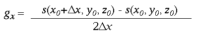
Another difference between 2-D and 3-D contours is that surface normals are generated at the vertices of the triangles. (Surface normals are important in 3-D graphics because they can dramatically improve the appearance of rendered objects.) To compute the normals, you use a central difference approximation to compute the gradient of the scalar values at each of the eight vertices of the cube. Then linear interpolation of the gradient from the cube vertices is used to compute the gradient at the triangle vertices along the cube edges. The central difference approximation at a vertex in the x-direction is given by the equation in Example 2 where s(x,y,z) is the scalar value at grid location x-y-z and x is the grid spacing in the x-direction. To compute the gradient vector, you use similar equations for the y and z components of the gradient, and then normalize the gradient to unit length. This unit vector can be used for Gouraud shading.
To demonstrate the application of contouring, we'll use the Visualization Toolkit (vtk) available at http://www.cs.rpi.edu/ ~martink. vtk, a C++ class library with a built-in Tcl/Tk interpreter for visualization and 3-D graphics (includes source code, data, and examples). The software runs on UNIX, Windows NT, and Windows 95. vtk 1.0 supports OpenGL rendering and includes executables for both Windows NT and Windows 95. Our book, The Visualization Toolkit: An Object-Oriented Approach to 3D Graphics (Prentice-Hall, 1996) describes the toolkit in more detail.
Creating 3-D visualizations and graphics with vtk is simple. Using either C++ code (or the Tcl interface), users create a few basic objects; see Listing One and Figure 4. The render master is used to coordinate device-independent graphics and to create rendering windows into which the final image is drawn. One or more renderers are created, which draw into the rendering window(s), and the rendered objects are represented via one or more actors. Each actor, in turn, has internal instance variables that refer to a property object (which controls material properties), a transform (which controls position and orientation of the actor), and a mapper (the geometric representation for the actor). If not specified, lights and an initial camera view are automatically generated.
In vtk, the mapper is the bridge between 3-D graphics and visualization. In visualization applications, the mapper's geometry is generated by processing data through a series of filters. Ultimately these filters construct graphics primitives (lines and polygons), which are then displayed for the user. To see how this works, let's look at three examples.
In the first example, we generate iso-surfaces of human anatomy from computed tomography (CT) scan data. In particular, we will use the data available from the National Library of Medicine Visible Woman project. This data is from a 59-year-old woman who willed her body to scientific research. The data consists of a series of computed CT slices at a separation distance of 1 mm. (Other Visible Woman project data was collected by freezing the body, cutting it at sections 0.3 mm apart, then photographing the sections. For more information, see http://www.nlm.nih.gov/ research/visible/visible_human.html.)
Listing Two, implemented in Tcl, shows how to extract an iso-surface corresponding to the bones of the feet. As you can see, this example is much like our previous example, except that we have used some filter objects to create a visualization network. This network is a data-flow network and is built by connecting various combinations of source objects (read/generate data), filters (ingest, process, and output data), and mappers (map the data into the graphics system).
Of particular interest in Listing Two is the vtkMarchingCubes filter. This object implements the marching cubes algorithm we described earlier, first ingesting a volume (that is, a stack of CT slices), processing the data, and generating triangles that represent the iso-surface. This data is then rendered, generating the image in Figure 5. Note that we have used an iso-surface value of 1224 to generate the bone surface. Using other values (600 is skin) we can generate other anatomical surfaces.
The data is quite large: 512x512x200 16-bit scalar values. We use an SGI Reality Engine to deal with this data. Also, we preprocess the data to strip off the header information according to the instructions in http://www.crd.ge.com/esl/cgsp/ projects/vw/. If you have a smaller system, you might want to try one of the next two examples instead.
Next, we'll look at a much more abstract application of contouring. We will generate iso-surfaces of flow pressure (pressure value of 0.4) in a combustion chamber. Figure 6 shows the final result, and Listing Three is C++ code used to generate the image. The data is from a simulation package run on a Cray supercomputer and uses a structured grid (or finite difference grid) to generate the solution.
Unlike the data in our previous example, which was regularly sampled (cubical cells), the combustor data is only topologically regular (hexahedral cells). With this change in the structure of the data, the case table and edge-interpolation process does not change, but the computation of vertex normals does. This points out that marching cubes can be adapted to any type of hexahedral cell, so the cells do not have do be cubical. Listing Three reflects these differences by using the more-general vtkContourFilter to perform the contouring and using the vtkPolyNormals filter object to compute the vertex normals. vtkPolyNormals computes normals at each vertex by averaging polygon normals that share the vertex.
Finally, we'll show how to use contouring to generate computer graphics models. The approach we use is called "implicit modeling."
The idea behind implicit modeling is that we take a simple seed geometry such as points, lines, or triangles, and generate offset surfaces by computing a closest distance to the seed geometry. In this case, the distance is our scalar value. The distances can be sampled over a grid of points to form a volume of data, much like the first example. Then, we can specify an iso-surface value that is simply the distance from the seed geometry to the iso-surface. Using marching cubes, we then generate the contour surface. Listing Four shows how to do this (using Tcl) to create the blobby "DDJ" surface in Figure 7. Here, we've used transparency to show the relationship of the seed geometry (the "DDJ" polygonal model) to the translucent blobby, or offset, surface.
Three-dimensional contouring is a simple yet effective technique for visualizing complex scalar data. For further information about contouring algorithms and additional C++ source code, see our book or visit http://www.cs.rpi.edu/~martink. Sample data (including the combustion data) is also available so you can try out your own contouring algorithms or applications.
for (index=0, i=0; i<4; i++)
    if ( scalar[i] >= value )
        index |= CASE_MASK[i];
Listing One
Listing Two
#include "vtk.hh"
main ()
{
  vtkRenderMaster renMaster;
  vtkRenderWindow *renWindow;
  vtkRenderer *ren;

  vtkActor *coneActor;
  vtkConeSource *cone;

  vtkPolyMapper *coneMapper;
  vtkRenderWindowInteractor *iren;

  // create a rendering window, renderer,
  // and 3D widget for object manipulation
  renWindow = renMaster.MakeRenderWindow();
  ren = renWindow->MakeRenderer();
  iren = renWindow->MakeRenderWindowInteractor();

  // create an actor; assign cone geometry
  cone = new vtkConeSource;
    cone->SetResolution(8);
  coneMapper = new vtkPolyMapper;
    coneMapper->SetInput(
                cone->GetOutput());
  coneActor = new vtkActor;
    coneActor->SetMapper(coneMapper);

  // assign our actor to the renderer
  ren->AddActors(coneActor);

  // draw the resulting scene
  renWindow->Render();

  // Begin mouse interaction
  iren->Start();
}
# Extract foot bones from visible woman
# get the interpreter interface tool
source vtkInt.tcl


# read the volume
vtkVolume16Reader v16;
  v16 SetDataDimensions 512 512;
  v16 SetFilePrefix "../slices/slice";
  v16 SetImageRange 1518 1734;
  v16 SetDataMask 0x1fff;
  v16 SetDataAspectRatio \
           0.72265625 0.72265625 1 # extract the bone
vtkMarchingCubes boneExtractor;
  boneExtractor SetInput [v16 GetOutput];
  boneExtractor SetValue 0 1200;
  boneExtractor DebugOn;
vtkPolyMapper boneMapper;
  boneMapper SetInput [boneExtractor GetOutput];
  boneMapper ScalarsVisibleOff;
vtkActor bone;
  bone SetMapper boneMapper;

# get an outline
vtkOutlineFilter outlineF;
  outlineF SetInput [v16 GetOutput];
vtkPolyMapper mapOutline;
  mapOutline SetInput [outlineF GetOutput];
vtkActor outline;
  outline SetMapper mapOutline;
  [outline GetProperty] SetColor 0 0 0;

# create the renderer stuff
vtkRenderMaster aRendermaster;
set ourRenderingWindow \
        [aRendermaster MakeRenderWindow];
set ourInteractor [$ourRenderingWindow \
        MakeRenderWindowInteractor];
set aRenderer [$ourRenderingWindow MakeRenderer];
  $aRenderer AddActors outline;
  $aRenderer AddActors bone;
$aRenderer SetBackground 1 1 1;

# interact with data
$ourInteractor SetUserMethod \
               {wm deiconify .vtkInteract};
wm withdraw .
Listing Three
#include "vtk.hh"
main ()
{
  vtkRenderMaster rm;
  vtkRenderWindow *renWin =
        rm.MakeRenderWindow();
  vtkRenderWindowInteractor *iren =
        renWin->MakeRenderWindowInteractor();

  vtkRenderer *renderer =
        renWin->MakeRenderer();
  vtkPLOT3DReader reader;
    reader.SetXYZFilename("combxyz.bin");
    reader.SetQFilename("combq.bin");

  // outline data
  vtkStructuredGridOutlineFilter outlineF;
    outlineF.SetInput(reader.GetOutput());   vtkPolyMapper outlineMapper;
    outlineMapper.SetInput(outlineF.GetOutput());
  vtkActor outline;
    outline.SetMapper(outlineMapper);

  // iso-surface
  vtkContourFilter isoF;
    isoF.SetInput(reader.GetOutput());
    isoF.SetValue(0,0.4);
  vtkCleanPolyData cleanIso;
    cleanIso.SetInput(isoF.GetOutput());
  vtkPolyNormals isoNormals;
    isoNormals.SetInput(cleanIso.GetOutput());
  vtkPolyMapper isoMapper;
    isoMapper.SetInput(isoNormals.GetOutput());
    isoMapper.ScalarsVisibleOff();
  vtkActor iso;
    iso.SetMapper(isoMapper);
    iso.GetProperty()->
        SetDiffuseColor(1,0.38,0.28);
    iso.GetProperty()->SetDiffuse(0.7);
    iso.GetProperty()->SetSpecular(0.4);
    iso.GetProperty()->SetSpecularPower(20);

  renderer->AddActors(&outline);
  renderer->AddActors(&iso);
  renderer->SetBackground(0.1,0.2,0.4);
  renWin->Render();
  iren->Start();
}