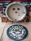
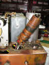
 Chassis as received. The round can on the right is the first IF
transformer. It was replaced with a unit designed for the 6A8 RF and
6K7 IF tubes.
 |
 Cardboard gasket.
 |
 As recieved.
 |
 The dial scale looks new. It is in great shape.
 |
 The tear down begins. The component locator on the Riders diagram
7-2 depict all square cans for the oscillator and antenna coils and IF
transformers.
 |
 I
suspect the Oscillator coil has been replaced or messed with. It has
a round can and too long lead wires (upper left) I
suspect the Oscillator coil has been replaced or messed with. It has
a round can and too long lead wires (upper left) |
 The damaged 455KHz trap coil. With out this the 455 oscillator
caused interference.
 |
 Hand repaired. A lot of breaks had to be soldered and rewound on the
coil.
 |
 Inspecting and replacing some lead wires on the oscillator coil. It
was later heated treated with a heat gun to drive off
moisture.
 |
 The band switch was cleaned, flushed and heated with a heat gun. All
coils were heat treated to drive off moisture.
 |
 Reconditioning of the dial scale reflector pan and pointers.
 |
 These are solid lacquer "Burn-In" sticks that are used to fill
in missing spots of veneer.
 |
 Burn-in stick used to fill in missing veneer.
 |
 600 grit wet dry sand paper and odorless mineral spirits are used to...
 |
 level and blend in the lacquer burn-in stick. The grit was advanced
to 900 and smoothed futher.
 |
 A new rubber U channel rubber dial glass gasket has been installed. That
should protect and keep the glass from rattling like a license plate on a
low rider.....
 |
 The corner molding has been toned a burnt ember.
 |
 The flat panels have been toned with a lighter brown toning lacquer.
 |
 Three
coats of clear lacquer then 000 steel wool buffed and coated two more
times. Three
coats of clear lacquer then 000 steel wool buffed and coated two more
times. |
 |
 I can't help but enjoy the tube glow!
 |
 The knobs were cleaned with mineral spirits and sprayed with
lacquer. Felt washers installed to protect the cabinet from
scratches.
 |
 The final finish was worked with paste wax applied with 0000 steel wool
then buffed to a shine.
 |
 Speaker grill vacuumed before reinstallation. The speaker screws have been
painted dark brown and the cut openings painted with black lacquer.
 |
