
![]()
![]()
![]()
![]()
![]()
![]()
![]()
![]()
![]()
![]()
![]()
![]()
|
|
|
| ||||||||||||||||||||||||||||||||||||||||||||||||||||||||||||||||||||||||||||||||||||||||||||||||||||
 |
 |
 |
 |
|
 I replaced the remaining dog bone and original carbon composition
resistors with new carbon film resistors.
I replaced the remaining dog bone and original carbon composition
resistors with new carbon film resistors. |
 The
restorer did a nice looking job. Unfortunately with beauty can come intermittent
operations. These leads were not twisted around the terminal posts
and a flux joint and not a solder joint can easily form. It has happened to
me. The
restorer did a nice looking job. Unfortunately with beauty can come intermittent
operations. These leads were not twisted around the terminal posts
and a flux joint and not a solder joint can easily form. It has happened to
me.
I went around the chassis securing lead wires and resoldering the joints. These joints may or may not cause problems. However with the client complaint of intermittent operation I am not taking any chances. |
 Just about every bench has a mirror.
 |
||
 The wire from the lower right goes through the solder terminal
straight. This is poor practice. A physically weak solder
joint.
The wire from the lower right goes through the solder terminal
straight. This is poor practice. A physically weak solder
joint. |
 This resistor shows flux on the right lead wire where it was pulled from
the solder blob. That flux is between the lead wire and solder. No
crimp and too little heat.
This resistor shows flux on the right lead wire where it was pulled from
the solder blob. That flux is between the lead wire and solder. No
crimp and too little heat. |
.  This
is the same resistor (left) reinstalled with crimped lead wires for a good
physical connection. This
is the same resistor (left) reinstalled with crimped lead wires for a good
physical connection. |
 The capacitor from the volume control wiper received the same wire wrap before
resoldering
The capacitor from the volume control wiper received the same wire wrap before
resoldering |
How can I boldly comment on these solder
joints? Well I have made the same mistakes that lead to
failures.
Taught at the EIHK, "Electronics Institute of Hard Knocks". |
 These
capacitors were changed. The 25pf is made by MicaMold
company. They are waxed paper, not mica and are to be
replaced. This brought the dial scale in to better agreement with the
indicator. These
capacitors were changed. The 25pf is made by MicaMold
company. They are waxed paper, not mica and are to be
replaced. This brought the dial scale in to better agreement with the
indicator. |
The
metal bar with tabs in the rear is a Candohm resistor. These are
know to go intermittent. I replaced the three sections not previously
replaced with ceramic/cerment wire wound resistors.  |
 RF
bypass cap was a regular capacitor. This is a UL approved Y2/X2
capacitor is specially made for this application. RF
bypass cap was a regular capacitor. This is a UL approved Y2/X2
capacitor is specially made for this application. |
||
 Power
cord before. Unsoldered and not wrapped around strain relief slots. Power
cord before. Unsoldered and not wrapped around strain relief slots. |
 Tinned wire ends and wrapped
around strain relief. I am just picky about some things. The
red dot when aligned with the hot side of the plug yields the least amount
of chassis leakage.
Tinned wire ends and wrapped
around strain relief. I am just picky about some things. The
red dot when aligned with the hot side of the plug yields the least amount
of chassis leakage. |
 Dial
scale lettering cleaned. Dial
scale lettering cleaned. |
 Frequency indicator stripped in
paint stripper and repainted white.
Frequency indicator stripped in
paint stripper and repainted white. |
|
 The
tuning shaft is rubbing against the band selector. It is dragging
the motor down. The
tuning shaft is rubbing against the band selector. It is dragging
the motor down. |
 I
loosened the shaft collar and allowed it to relieve the tension. I
loosened the shaft collar and allowed it to relieve the tension. |
 Adjusted
the play in the band selector bracket to free the motor driven tuning
shaft. Adjusted
the play in the band selector bracket to free the motor driven tuning
shaft. |
 |
 |
 |
 Lubricated
the shutter mechanism. Lubricated
the shutter mechanism. |
 Pivot points and shafts.
 |
 Drive pulley to the capacitor gang is quite cruddy.
 |
 Oil saturated drive belt.
 |
 Alcohol
cleaned drive belt with rosin (It looks the same as the oily belt).
Use a few drops of denatured alcohol to dissolve and transfer the rosin to
the belt. Alcohol
cleaned drive belt with rosin (It looks the same as the oily belt).
Use a few drops of denatured alcohol to dissolve and transfer the rosin to
the belt. |
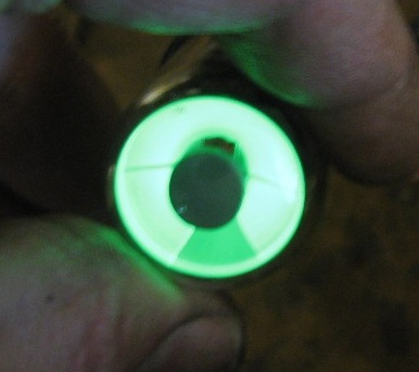
 Original
tuning indicator is a bit dim. This picture is over exposed. Original
tuning indicator is a bit dim. This picture is over exposed. |
 Home Brew pin converter to an octal socket eye
tube.
Home Brew pin converter to an octal socket eye
tube. |
 6E5C
Brand New Russian made eye tube. 6E5C
Brand New Russian made eye tube. |
|
 |
 Much
brighter! Much
brighter! |
 Touch
up some scratches. Touch
up some scratches. |
 Blend
matching colors. Blend
matching colors. |
|
 Once
you make one adjustment another goes out of alignment. The shutters
are hitting this shaft splice and interfering with the band switch's
ability to
settle in to on of the bands. Once
you make one adjustment another goes out of alignment. The shutters
are hitting this shaft splice and interfering with the band switch's
ability to
settle in to on of the bands. |
 The shaft splice had to be clearance (ground down) to allow the shutter to
fully open thus allowing the band selector shaft to fully rotate into the
detent. Now you begin to figure out why other things (motor driven tuning
shaft) were out of whack.
The shaft splice had to be clearance (ground down) to allow the shutter to
fully open thus allowing the band selector shaft to fully rotate into the
detent. Now you begin to figure out why other things (motor driven tuning
shaft) were out of whack. |
|||
 The
dial scale alignment is still a bit off near the middle of the
bands. Heating of the oscillator coil and the band switch wafers
drive off moisture. This helped. The
dial scale alignment is still a bit off near the middle of the
bands. Heating of the oscillator coil and the band switch wafers
drive off moisture. This helped. |
The band switch wafers were washed and scrubbed (gently) with a tooth brush to get off any crud. The Denatured alcohol washed away contaminates and oil The heat gun drove off the alcohol and any moisture. This improve the dial scale frequency alignment. |  This is a Windows Media file. A video of the motor tuning
drive. It is 4 minutes long.
This is a Windows Media file. A video of the motor tuning
drive. It is 4 minutes long.
|
||

I am going to look for a new outer bezel. |
 This outer bezel is in some rough shape.
 |
 Sooner
or later one will come up for sale. Sooner
or later one will come up for sale. |
 |
|
 |
 |
 |
 |
 The output transformer
works. I used it to diagnose and test the above chassis.
The output transformer
works. I used it to diagnose and test the above chassis. |
 This needs re-coned. But it works. Sounds crappy but
works.
This needs re-coned. But it works. Sounds crappy but
works. |
 The Eye tube socket adaptor for the 6E5C octal tube.
 |
 The antenna terminal strip has been replaced and mis-wired. Also
seen is the rectifier socket. Jumpers have been added to accommodate
a different rectifier pin out. All the operating parameters are the
same. And the jumpers accommodate the original speced
tube.
The antenna terminal strip has been replaced and mis-wired. Also
seen is the rectifier socket. Jumpers have been added to accommodate
a different rectifier pin out. All the operating parameters are the
same. And the jumpers accommodate the original speced
tube. |
 A
little fuzzy but properly wired. It makes a great improvement on the
non BC bands. A
little fuzzy but properly wired. It makes a great improvement on the
non BC bands. |
|
 I
color matched the black dial scale, scraped off some rust and touched up
the scale. I
color matched the black dial scale, scraped off some rust and touched up
the scale. |
 |
 |
||
Contact me including your thoughts and comments. 135,912 unique web site visitors (14,499,000 hits) from October 2004 through August 2011. Copyright © 2004 - 2012. All rights reserved.
|

