![]()
![]()
![]()
![]()
![]()
|
|
|
This is a Hammarlund HX-50 transmitter just into the shop for recapping and alignment. Capacitors, some 2 watt and power resistors are on order from Mouser. Initial cold checking found quite a few high wattage (over 1/4 w) out of tolerance.
Big Caps replaced for 750v supply
Issues in the HV RF cage
The HV RF cage was full of cigarette tar. When unsoldering components the smell of cigarette smoke wafted up from the soldering gun. All the components have been cleaned with contact cleaner and denatured alcohol. The chassis and RF containment box was also cleaned.These are pictures of the parallel combination of L115 and R181. It appears that someone changed the turns arround the 47 ohm resistor and shortened it. Additionally it appears that two windings were shorted with solder.This must be resolved before over 700 volts of EMF is restored to this unit. Schematic here: http://bama.edebris.com/manuals/hammarlu/hx50/Power Supply ChokeWell am back on the case this day in Feb 07. It has been a year letting this rig "breath". While going back and checking all voltages I discovered the negative bias voltages to be quite lacking on several tubes. So checking back to the negative bias supply I found there to be insufficient negative voltage on the half wave rectified bias supply.Checking further back I found 190 vac across the choke (L112). Well that would detract from the negative voltage power supply. The choke measures 97 ohms cold. No luck on Google for the L112 choke specs.
Update on Choke L112 "swinging chokes"You can't beat the new groups! Great guys willing to help. Just ignore the Flame wars and Spam. I received several private emails and a bunch of replies in the news groups. Below is a helpful sample.
I turns out this bias circuit worked after replacing R 168 and R172. i had originally replaced these resistors. So perhaps I had a cold solder joint. Well come on now ....that happens to the best of us once in a blue moon.IT'S ALIVE! Feb 23After replacing R172 and pulling out an added (mod) series resistor with R143 rheostat (Idle tube bias) the Screen bias on the final came up to -76 volts. Not all negative bias voltages are as documented. BUT putting the rig on 20 meters and tuning up the output produced 20 watts of clean CW. I have been reversing numerous modifications to restore this unit to original. This was just one more mod to remove.The 80m band was dead but the scope showed adequate input to the final 6DQ5 sweep tube. All bias voltages looked good. The problem was a shorted C207 100pf 1000v cap switched in parallel to the Plate Tuning variable air capacitor. I temporarily replaced that cap with one of 500v rating. I will order a new 1000 volt cap soon. Once replace the 80 meter band showed 20watts output CW.The 10m "B" and the 40 meter bands have dead crystals in the oscillator section. All other bands have output from 10 to 15 watts. The unit needs a good re-alignment at this point and at least two new crystals.I think there may be a few other bad caps in the output network. I have to rotate the plate control full clockwise to peak the output into a 50 ohm 100 watt dummy load. But for now I am quite happy to see watts output.Hint .
VFO Dial Scale adjustmentAdjusting the VFO so it lines up every 100khz can be tricky. Knifing of the variable cap was needed. Knifing is where the outer two rotor veins are bent in or out to smooth out the response of the oscillator. All the adjustments interact with the maximum capacitance position of the cap. But with patients and care it is doable.
Neutralizing the Sweep tubeWow. What a task. I am not done yet. There seems to be a stability problem. I have the scope monitoring the output for a clean sine wave. That helps a lot. If not for the scope I would have walked away thinking Job Well Done to only hear the wrath of other hams about interference. I am chasing the parasitic suppressor found in the plate circuit.
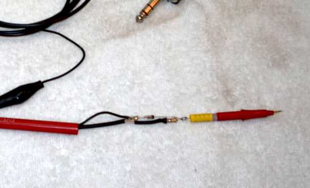
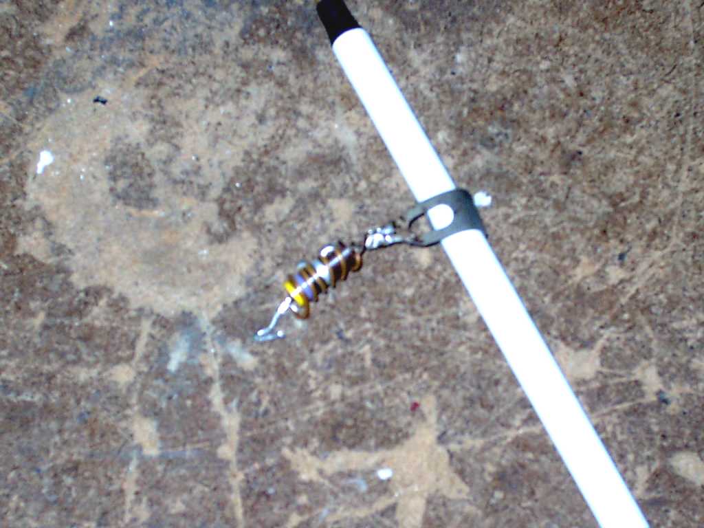
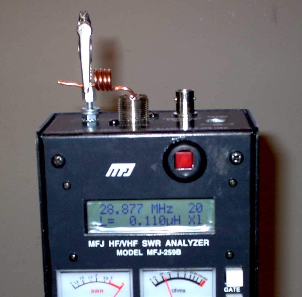
Finding a non inductive 47 ohm 1w resistor for the suppressor is next. The original 10% resistor is a bit toasty and measures above 75 ohms. I will order a carbon comp for the final installation. A metal oxide resistor are alleged to have little inductance at this frequency. Carbon Film resistors with the spiral trace of carbon wrapped around a ceramic core will show inductance at higher frequencies. That in parallel with the inductor drops the overall inductance. That is where the harmonic instability is occurring.Finding new 1 watt carbon composition resistors was a challenge. I found plenty at ham fests. However, they are typically way out of tolerance. I just refuse to use NOS resistors and capacitors in restorations. You are just installing "Time Bombs" waiting for a quick failure. If you demand originality there are ways to create restoration looking capacitors and resistors. See the bottom of this hyper linked page on reproduction resistors.I came across an OHMITE offering of carbon ceramic at Mouser. Advertised to be a non inductive replacement for carbon comps. The carbon ceramic resistors came in and were installed in the suppressor. I reused the original coil that was wrapped around the 47 ohm resistor. It works fine.I tried the unit out and made a 75m contact to VA during their March VA QSO contest. What a thrill to log that one in! Well 10m c band is not working. So back out to the shop.
Second mixer and RF driver stage alignment page 30.An important discovery. When performing alignment 7-8-1 on page 33 (you can find the manual at BAMA) Second mixer and Driver stage, one must complete the adjustments of both plate slugs (The 2nd mixer transformer and the drive transformer) at one particular frequency then change to the higher frequency and adjust the output slugs. The plate slugs are the top slugs nearest the chassis. The output slugs are closest to the bottom or the under side of the chassis.You must peak (bounce back and fourth) from the 2nd mixer plate slug and the driver plate slug with out touching the frequency as though you are adjusting the top and bottom slug in an AA5 IF transformer to find resonance. I made this mistake at first.Once the low frequency of that band is peaked change the generator frequency and peak both output slugs. alternating from 2nd mixer to driver stages until output is peaked. Then return the the lower frequency, take a sip of coffee and spend about 5 to 10 minutes repeating the low and high frequency adjustments until you coffee needs refilling and no more improvement can be seen.I had to back out all the slugs and start from scratch. Move the plate or top slugs up and move the output sluge to the bottom. The first peak of the slugs is far from the final position.Example:
The amp seems a lot more stable. I can easily tune up into a dummy load and see decent wattages. A tweak of the neutralizing cap C188 was needed to keep the final from running away in oscillations. Use the Neutralization procedure in the book.Here is a link where some great Hammarlund cabinet restorations have been accomplished.
| |||||||||||||||||||||||||||||||||||||||
Contact me including your thoughts and comments. 135,912 unique web site visitors (14,499,000 hits) from October 2004 through August 2011. Copyright © 2004 - 2012. All rights reserved.
|