![]()
![]()
![]()
![]()
![]()
![]()
![]()
![]()
![]()
![]()
![]()
![]()
![]()
![]()
![]()
![]()
![]()
![]()
![]()
![]()
|
|
|
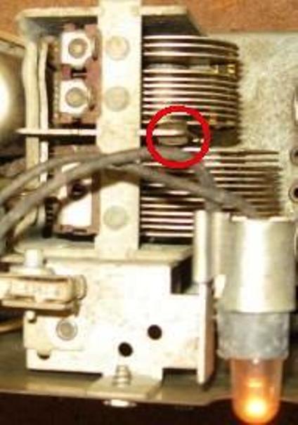
Philco 41-221Manufactured about April 1941
This radio receives both Broadcast and Short Wave band.
Most of the insulation has deteriorated and is crumbling off. About 30% is OK. Philco seemed to use two types of rubber for insulation. It was 1940-40 during WW2 when this radio was manufactured. Materials were in short supply for consumer goods. This is a rather common occurrence with radios manufactured during these years.
Tom is an artist! Click on this paragraph and go to his new web site. There is always a few chassis that just don't make it easy to align. I have not been defeated yet! R21 had the wrong value installed and replacing the 14AF7 rendered the radio stable, no squegging. Once replaced all aligned in easily.
| ||||||||||||||||||||||||||||||||||||||||||
Contact me including your thoughts and comments. 135,912 unique web site visitors (14,499,000 hits) from October 2004 through August 2011. Copyright © 2004 - 2012. All rights reserved.
|