![]()
![]()
![]()
![]()
![]()
![]()
![]()
![]()
![]()
![]()
![]()
![]()
![]()
![]()
![]()
![]()
![]()
![]()
![]()
![]()
|
|
|
The Philco 39-30 looks similar to the 40-150 table top. The complete schematic is found here at Nostalgia Air. This is snippet from the web site:
Push Buttons .I should have mentioned this sooner. If you contact Larry at
|
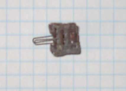
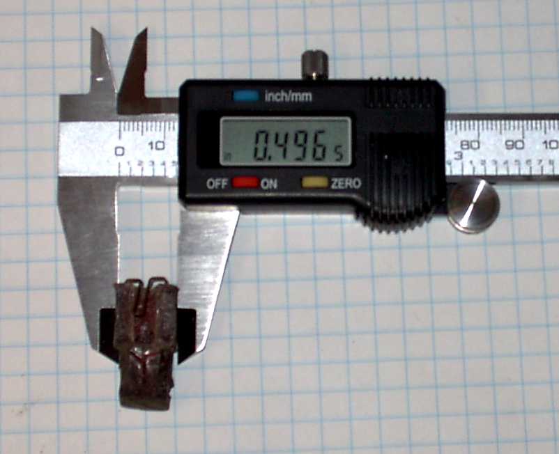
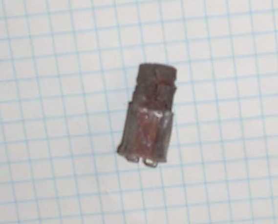
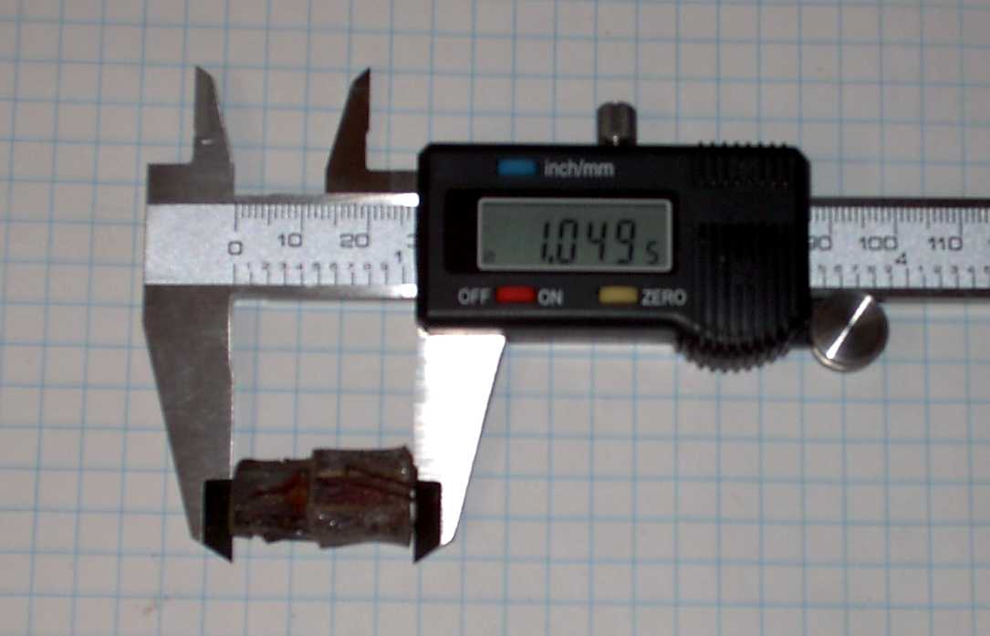 This is a little over an inch.
 |
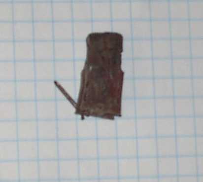
 I bet this was originally a full half inch. This plastic shrinks
over time.
I bet this was originally a full half inch. This plastic shrinks
over time. |
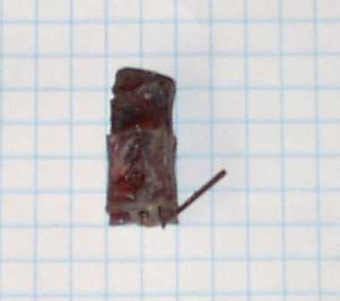 This
looks and acts like a retainer clip so the button does not fall into the
chassis. This
looks and acts like a retainer clip so the button does not fall into the
chassis. |
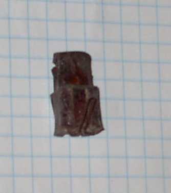 |
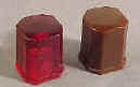
 Original
|
Click on this picture to get to Larry's web site and order some of these longer buttons.
|
|
 This is how the buttons where installed in the bezel. There is a metal
box frame that holds the buttons in place.
This is how the buttons where installed in the bezel. There is a metal
box frame that holds the buttons in place. |
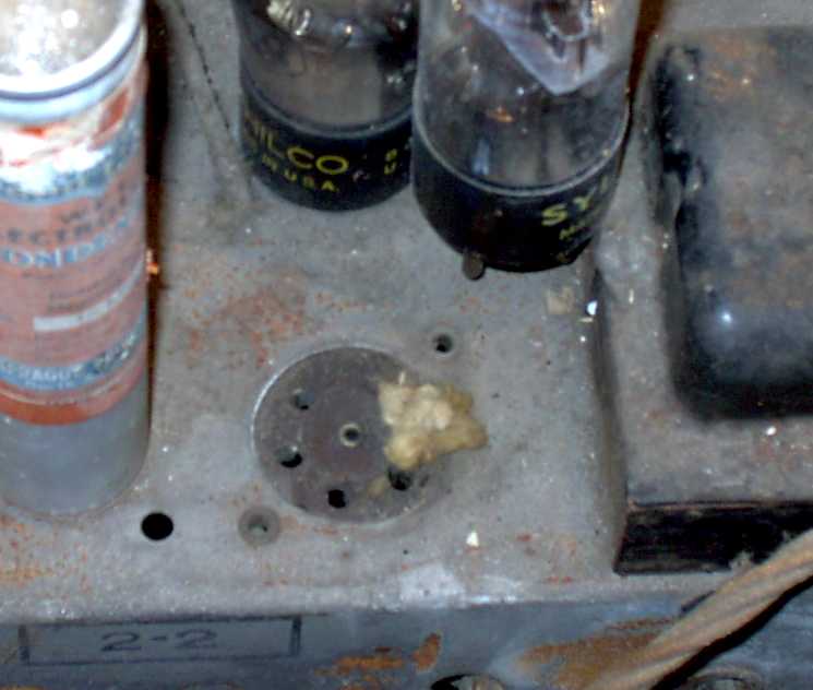 What is this bit of fiber glass insulation doing here?
 |
 Burned socket. Indicative of long term arching. Not a
problem. I have replacement sockets. All the wires on this
socket need replacing anyhow.
Burned socket. Indicative of long term arching. Not a
problem. I have replacement sockets. All the wires on this
socket need replacing anyhow. |
 Rather clean underside. Some one has bridged new capacitors across
the dried out can caps. A common practice. But not in my
shop!
Rather clean underside. Some one has bridged new capacitors across
the dried out can caps. A common practice. But not in my
shop! |
 A power wire brush will make short work of this rust.
 |
 Evidence
of squatters. Evidence
of squatters. |
 The bottom front has a shaped piece of trim. The 39-30 has inlayed
veneer.
The bottom front has a shaped piece of trim. The 39-30 has inlayed
veneer.
Easy to reproduce dial scale cover. |
 Water stain.
 |
 The
missing veneer chip should be easy to fix. The
missing veneer chip should be easy to fix. |
Contact me including your thoughts and comments. 135,912 unique web site visitors (14,499,000 hits) from October 2004 through August 2011. Copyright © 2004 - 2012. All rights reserved.
|