![]()
![]()
![]()
![]()
![]()
![]()
![]()
![]()
![]()
![]()
![]()
![]()
![]()
![]()
![]()
![]()
![]()
![]()
![]()
![]()
|
|
|
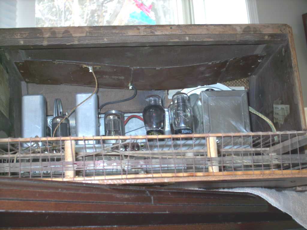
I received a link to Steven's site some time ago when I had a Philco 40-180 chassis to restore and no antennae. The information on his site seen below was very helpful in construction a replacement. I frequently use the antenna for bench repair and alignment. Very little alignment "tweaking" is needed once the chassis have been reinstalled with their original antennae. (Rotation Antenna page.)The Short wave antenna (a simple loop of about 24 inches or less of wire suspended by stiff cardboard) is not shown here. Images of it will be added later. Message me if you need a picture sooner. This loop is stapled to the top of the cabinet above the chassis.This internal short wave antenna will fit into a 40-150, -180 or -190. Use a stiff solid wire for the antenna loop. Hot melt glue will help assembly. You can use nut washer and bolt combination for the two terminals or washers and pop rivets. Use stranded wire for the leads with spade crimp or solder ends.
Please see site address http://www.geocities.com/reevesradios/150a.html for original document. Send Steven at http://www.geocities.com/reevesradios/ a thank you note.Break out the tape and hot melt glue guns and have at it!
Reeves Radios Home Page1940 Philco 40-150
  |
Contact me including your thoughts and comments. 135,912 unique web site visitors (14,499,000 hits) from October 2004 through August 2011. Copyright © 2004 - 2012. All rights reserved.
|