![]()
![]()
![]()
![]()
![]()
![]()
![]()
![]()
![]()
![]()
![]()
![]()
![]()
![]()
![]()
![]()
![]()
![]()
![]()
![]()
|
|
|
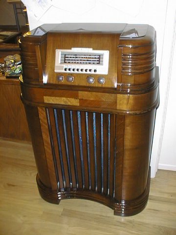
This restoration has been performed by Dan C. He kindly sent me his restoration story of a 40-180. I think he did a great job. Have a look below.
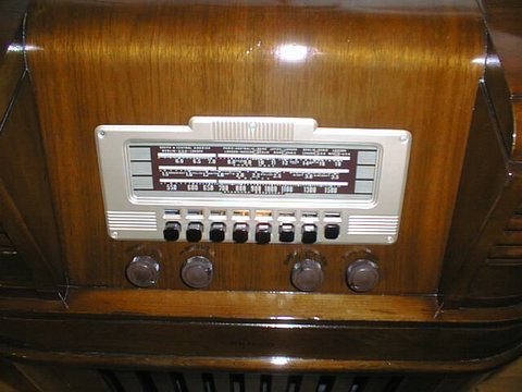
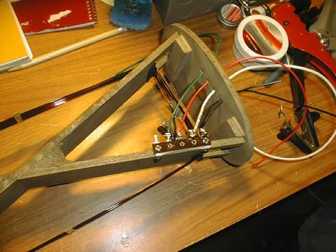
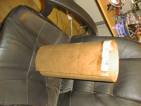
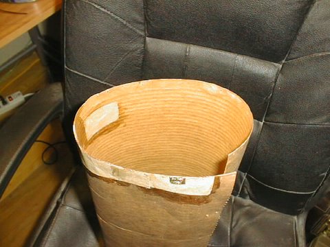
Hi Paul, I have recently finished my restoration of a Philco 40-180 which I have dragged around the country for the last six years. I wanted to share my experiences with the restoration with you in hopes that it might help you or others who are working on similar units. I am sending you photos of the restoration in a separate email. I also owe you a debt of gratitude, not only for your excellent website, but also for your posts on the antique radio/phono [news:rec.antiques.radio+phono] group. It seemed that when I had a question about these models, you had already asked it and either somebody else answered it or you figured out the answer yourself. So without further adieu, here are my notes about the restoration. History of the Radio and MeI acquired this console from an elderly gentlemen in North Carolina who was physically unable to continue working on radios. I think that I paid him $30. He had made his living as a radio repairman since the 1940’s and eventually serviced mostly T.V.s until he retired. He had some neat test equipment that unfortunately he would not sell. I have a degree in Electronics Technology and have made my living as an Electronics Tech., but I’m not working in that field now. I have restored many radios and amps, but never done a console because most of them cannot be easily shipped around the country and the market is much more limited for them. I am forced from time to time to sell my radios to raise funds, so I always look at the eventual potential to sell a radio that I work on. This Philco was an exception, since my wife has gotten used to using it as a convenient place to stash her purse and keys on and is kind of fond of it now. The condition of the radio was not great, but not terrible. It appeared to be complete, but the exterior finish was pretty bad. Moving it around the country several times did not help its condition any. The Electronics RestorationI decided to follow your protocol and replace all of the resistors, caps and rubber coated wiring. I usually don’t replace everything, but since I will probably keep this radio, I decided to make it a total restoration. The electronics work was really straight-forward and did not present any particular problems. You were right about the values of the resistors being way off of spec. I found that the resistors were at least 30 -50% higher than called for. I did the filter caps a little different than you did. I used a terminal strip and wired the caps in one section, rather than place them back in their original locations. (See photo) I was a little concerned that I might have hum problems, but I have detected absolutely no hum or distortion at all. More about the sound later. The only problem I had was the octal socket for 6JBG. It is made out of stiff cardboard rather than Bakelite and I kept twisting out the socket contact points when I was desoldering wires. I simply used epoxy and glued the sockets back in to their appropriate location. I also found that the grommets which insulated the chassis, variable cap and push-button section from the chassis could be replaced with Radio Shack’s rubber grommets which comes in a variety pack of several different sizes. I initially only replaced the Mica caps that you recommended, ie Caps 22, 23 and 24. However, as I was aligning the radio, I just felt that something wasn’t right. I was having a hard time making the dial track precisely. I went back to the schematic and started to suspect the Micas that act to reduce capacitance ( in series) for the SW circuit. I checked their capacitance with my LCR meter (out of circuit of course) and found that several of them were way off spec. For example, number 6 which is supposed to be 250pf read only 28 pf. I decided to replace all of the Micas with the exception of 5 & 20 which were pretty close to being right on spec. Most of the bad Micas were made by Micamold. In the future, I will always suspect this particular brand of Mica caps. In actuality MicaMold capacitors are plastic covered paper capacitors. Just replace all of them with the other tubular wax/paper caps. Paul.Fortunately, the IF and power transformers were ok, as were all of the tubes, although I replaced 6JBG (Oscillator) because I thought it was a little weak, although it tested good on my tester. Your information on replacing the conditioning caps was excellent. Rather than use a heat gun, I used my wife’s hair dryer and kept applying heat to the outside of the Bakelite case until I was able to dig the tar out with a small screwdriver (see photo). I used .01 safety caps from JustRadios.com and it was really easy. I would urge anyone who needs to replace line caps to read Dave’s excellent page on the JustRadios.com website about line caps and the correct ratings to use depending on the application and how they are wired. This in one job that you must do right. I replaced the dial cord and rewired the dial lamp. Both were really easy jobs. I also replaced the extruded rubber that goes around the edges of the dial glass which I purchased from RadioDaze.com. I replaced the push buttons with a wine-colored set that I got from RadioDaze.com. I then took the antenna apart and replaced the Mica cap and 10K resistor and all of the deteriorated wires. Again, no big deal—although I did have to repair one torn section of the brown paper outside skin with a patch made out of a small piece of grocery bag affixed with rubber cement. Cabinet RestorationI had no intention of stripping the case and doing a ground up refinishing job because I don’t like using stripping chemicals in that type of volume. I used to strip cabinets with some stuff made by 3M that was green and safe enough to use without gloves. It was slow, but very safe and didn’t have to be used with a respirator. I could get it at Lowes, but they stopped carrying it and I have not been able to find it anywhere else. So, I just decided to wing it and hope for the best. I first removed the bezel and then cleaned the entire cabinet with Murphy’’s Oil Soap. It was very, very dirty. Then, I covered my kitchen table with an old sheet and laid the cabinet on top of the table like a coffin. I then took some Minwax stain in Walnut color and proceeded to apply it with one rag and then wipe it off quickly with another rag. After I had done the entire cabinet, I was amazed with the results. It was not perfect, but it looked about 200% better. Next, I applied seven coats of Deft gloss lacquer waiting two hours between coats, but not sanding in between coats in accordance with Deft’s website information. I of course used a respirator and chemical gloves and would urge anyone spraying lacquer or any paint to do the same. Your brain cells will appreciate it. Next, I wet sanded the entire cabinet with 600 grit 3M waterproof sandpaper being careful to not get too aggressive. I just tried to get rid of the dust hairs and remove the lacquer gloss. I then waited a week for the finish to harden. Then, I rubbed out the finish with Meguiar’s Step 1 Paint Cleaner (or you could use auto rubbing compound) with an old t-shirt and then rubbed it out again with Meguiar’s Step 2 Polish, also using an old t-shirt. Finally, I applied a coat of Johnsons’ pastewax and buffed out the shine by hand. The results were much, much better than I ever expected to receive (see photos) The finish looks like an expensive piece of furniture now and yes, I can see myself smiling in the reflection. BezelI did strip the bezel with some stuff called Bulls Eye Safer Paint & Finish Remover in a spray bottle that I got at Lowes. I used gloves and a respirator and it worked very fast. I then removed the old paint with a plastic putty knife and washed the bezel in soap and water. I then went down to Kraigen’s Auto store and bought some Dupli-Color DSGM457 Light Driftwood Metallic spray paint and the appropriate Dupli-Color primer. I painted the bezel with about three coats of primer and three coats of paint. It looks to me to be identical to the color that you used on your bezels. I made my station call letters with Word using an inkjet printer. Very easy and they will be easy to change. AlignmentI aligned the unit basically following Philco’s procedure. Everything was straightforward and the dial tracks very close and reception and sensitivity are fabulous. The only puzzling item was the trimmer cap number 3 on the back of the chassis had not affect whatsoever on the output of the radio. I used my usual insulated screwdrivers and a ¼ inch nut driver to align the unit. I also set the push-buttons with the help of my signal generator. Fidelity and ReceptionIn a word, incredible. When I fired up the radio for the first time after aligning it, my wife came in the room and asked me whether it was a stereo system. We have a station in the Sacramento area that plays old standards like Frank Sinatra, etc. and l just sat back and was amazed at the sound coming out of the radio. Then, I tried the shortwave. Without any external antenna, I tuned across the dial and picked up the 10 MHz time signal dead bang on the 10 MHz dial location. I then kept tuning and found the 15 MHz time signal very close to the 15 MHz dial location. Needless to say, I am very impressed. I now realize that AM radio died as a music medium at least in part because no one has decent radios anymore to listen to the music. SummaryThat’s about it. I would call this an interesting, but not particularly hard restoration. Thanks again for your insight and great website. Feel free to distribute my comments and photos on your website or in the radio forums if you think appropriate. Dan C.
40-185Steve also completed this 40-185. Another fine example of a radio restoration. And I am partial to Philcos.
Now this gives me great satisfaction. To be able to help others. This is the purpose of this web site.Paul.
|
Contact me including your thoughts and comments. 135,912 unique web site visitors (14,499,000 hits) from October 2004 through August 2011. Copyright © 2004 - 2012. All rights reserved.
|