![]()
![]()
![]()
![]()
![]()
![]()
![]()
![]()
![]()
![]()
![]()
![]()
![]()
![]()
![]()
![]()
![]()
![]()
![]()
![]()
|
|
|
Philco Model 45
Manufactured in 1934 and sold for $49.95. In 2009 that would be $773.
This is a dual band broadcast AM and short wave. I must say this is one of the more beautiful radios that I have had the pleasure to get to know.
I believe that the original finish of a radio cabinet should be conserved and/or maintained. That way you have a great period piece and it keeps it's vintage cabinet furniture value. However, that original finish has to be maintained at the start of the ownership. In this case that would be some time around 1934. (It is conceivable a prior owner listened to the news cast about the Pear Harbor attack. And years later the end of the war.) This cabinet finish was not original (to the best of my observation and opinion).For some archived radio shows click here. RADIO IN 1934 is a link to what was happening about that time.
I searched my camera and computer memory. Unfortunately I must not have taken an original picture. Up close one could see missing, flaking lacquer and exposed wood toner or stain. The condition tugged at my heart. It needed TLC. I advised the owner and proceeded with his consent.
After parts replacement the alignment was quite straight forward. IF set at 460khz.There are two IF transformer capacitors. One adjusted with a screw and one adjusted as a nut. The nut looks to be a lock-nut for the screw. But it is NOT. Those "nuts" were way out of adjustment. The screws were just about right on.I surmise some one adjusted the IF "screws" but missed the second capacitor NUT adjustments. I used a piece of heat shrink tubing to get around the nuts with out shorting the caps to the IF can case.
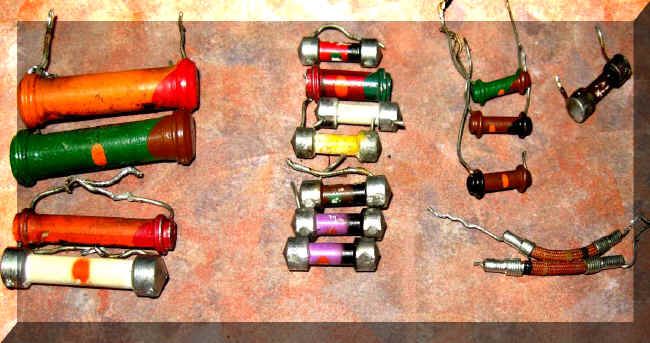
Ever once in a while I measure all the resistor that I replace for a restoration. I was tempted to leave the good resistors but I do not want to take risk of having a resistor go bad after I ship the radio home. I hate (and embarrassed) about failures of my oversight.
"Dog bone" resistors. 20% tolerance.
"But Paul", you say, "most of these resistors are in tolerance. You should have left them in the radio. That way it is more original."Sure, most of these resistors are in tolerance (20%). The capacitors are not original. The new heat shrink wire insulation is not original. My problem is when they go out of tolerance the radio will be back home with the owner. It will then cost another 100 bucks round trip for a 7 cent resistor! How irritating is that? They all get replaced. | |||||||||||||||||||||||||||||||||||||||||||||||||||||||||||||||||||||||||||||||||||||||||||||||||||||||
Contact me including your thoughts and comments. 135,912 unique web site visitors (14,499,000 hits) from October 2004 through August 2011. Copyright © 2004 - 2012. All rights reserved.
|