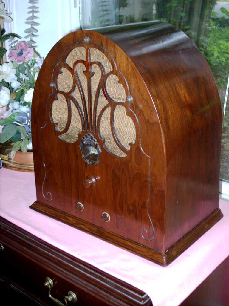
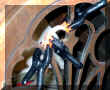
This Philco 20 must have manage to
irritate the
owners dog one day. So it took a chunk out of the grill lattice
work.
|
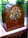
The flash brought out the wrinkle in the grill cloth and
illuminated the backing board. these are not visible with out a
flash.
|

There are multiple layers of lacquer and
hand rubbed paste wax.
|
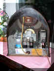
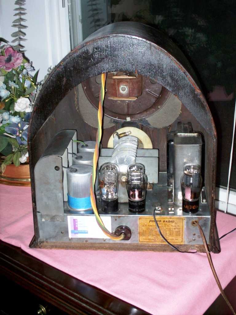
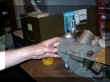
Nice interior shot. Don't worry. My repair
sticker is on a magnetic sticky card.
|
Before
|
After
|
Philco Model 20 (1934 vintage) is a TRF (not superhetrodyne) radio. It
has all tuned circuits to receive and detect the audio from the air. Here
are some pictures of the restoration.
Electronic Restoration
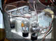
The only restoration challenge is restuffling the large multi section
capacitor. There in which the real challenge is minimizing the melted tar
or pitch. I held the capacitor in front of a LP space heater and kept it
moving. Softening of a layer that contacts the inside of the can is the
goal.
I removed this capacitor from the chassis. I was later told this is unnecessary.
You only have to unbolt the retaining screws and pull up on the can while gently
restraining the bottom cover. It separates. The bottom is not
affixed to the upper can. Then clip the wires, clean out the can and add
new capacitors.
The smallest electrolytic that I had on hand was 10 uf. They work
fine. 10 uf is well with in the capacitor specifications of the #80 rectifier
tube (I always check). I used a Polypropylene 0.1 uf 630 volt as well for
a direct value replacement of .13 uf across the choke. Riders
Vol 2 page 2-3,4 Vol 1-6 from Nostalgiair.org

|
|
|
|
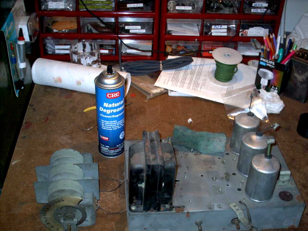
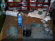
This radio seems to have been stored near a coal shed.
Typical seventy years of dirt.
|
|

|
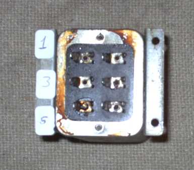
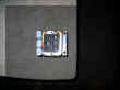 Bottom view of multi section can capacitor.
|
|
 A fully restored, operational chassis!
|
|
Resistors
I found all but two resistors out of tolerance. Most beyond 100%.
I replaced the resistors with two 1/2 watt in parallel to obtain 1 watt dissipation.
Of course the individual resistors wattage are double the needed value. I have
saved the original resistors in the event that someone would later
intend to make reproduction "dog bone" resistors to maintain the
vintage look.
 And
how about those Dog gone Dog Bone Resistors? Try
Syl's web site. And
how about those Dog gone Dog Bone Resistors? Try
Syl's web site.
Bakelite Capacitors
After removal, clip the lead wires exiting the rivets, heat with a 40 watt
focused spot light, and push the insides out with a small stick through a rivet.
I have broken a case before, by using a screw driver.
Clean with contact cleaner and solder in new caps. Season to taste and
Replace. Check your schematic or see, http://www.philcorepairbench.com/partinfo.htm
and select the Bakelite Blocks for what is inside. Thanks to the Philco
Repair Bench for maintaining such a valuable Resource!
Alignment
Alignment is simply putting the RF generator on 1400 khz, setting the dial on
140 (1400 khz), placing a loop of wire near the antenna (a length of wire) and
adjusting the three compensating capacitors mounted on the variable air capacitor.
Some models only have one or two.
If tracking is off, bending of the outer most disc of the air capacitor is
needed. This radio tracks accurately. No adjusting is needed.
However, several, not all, bent plate sections were apparent on the center
section rotor.
Cabinet
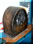
 Before stripping. This is the condition as originally found. Normally
I try to save the original finish. But as you see there was little
to salvage. This radio was destined for the dumpster.
Before stripping. This is the condition as originally found. Normally
I try to save the original finish. But as you see there was little
to salvage. This radio was destined for the dumpster.
|
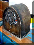
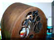
 New arch added. Veneer, removed from under a trim
strip did not match. A new piece of wood backed veneer was used in
the final repair. It was quite hard to color match this new veneer. New arch added. Veneer, removed from under a trim
strip did not match. A new piece of wood backed veneer was used in
the final repair. It was quite hard to color match this new veneer.
|
 After stripping.
If you look close the toned wood filler can be seen. It is not as
red in sunlight and interior lights. The camera's flash seems to
bring out the Red tone of the filler.
|
Finished radio. The tinted wood filler takes the
color matching markers well. Better than stain.
The Tan knob felts have been changed to Dark Brown.
They no longer contrast with the finish.
|

|