![]()
![]()
![]()
![]()
![]()
![]()
![]()
![]()
![]()
![]()
![]()
![]()
![]()
![]()
![]()
![]()
![]()
![]()
![]()
![]()
|
|
|
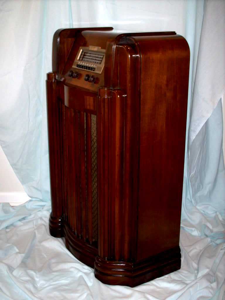
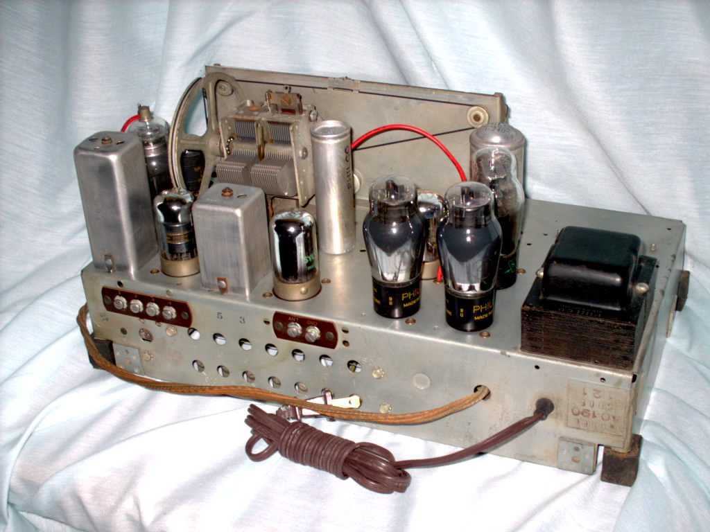
This is a Philco 40-190. The 40-190 has a distinctive Art-Deco look to the cabinet. Electronically it is virtually identical to the 40-150 and 40-180. The Riders schematics detail the differences in the chassis. The differences amount to an added antenna coil for the 40-150 and/or a tube change. One of the revisions includes a series resistor to stop oscillations with a particular tube on the SW band. This radio has a rotating antenna for broadcast bands. Some times this
antenna is missing. Or the service bench needs to mock one up. Here
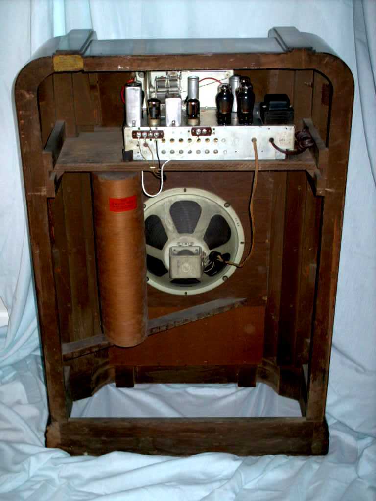
are some details. See what is inside
that rotating antenna Shop Pictures Before
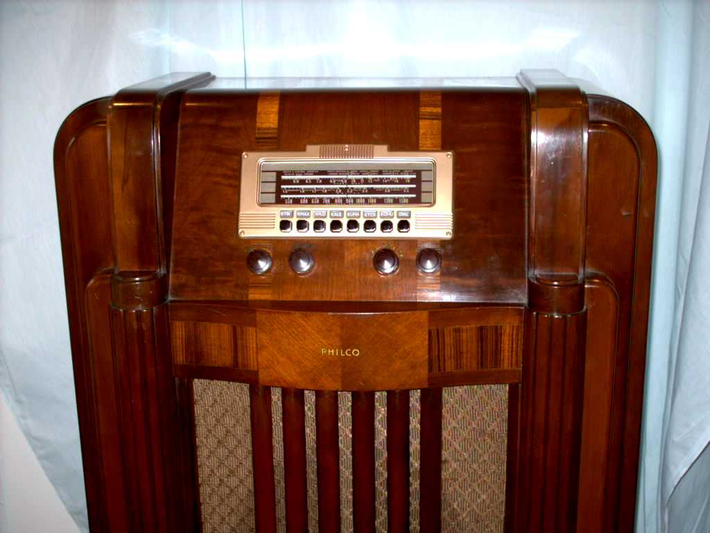
CleaningI tried several methods to clean the cabinet. I started with GoJo. It did not remove much of anything. Next I tried a rag and alcohol. The rag turned an instant shade of dirt!. Later I moved to four ot (#0000) steel wool and alcohol. With the 0000 steel wool the pickled, orange peal finish stripped right off. A combination the dirt, a coating of dark tar like matter, all the paint splatter, crayon marks and grime around the control knobs also came right off. Underneath is a beautiful three dimensional, grain pattern finish. The type of finish with visual depth and grain that catches the light and shimmers as you move your head side to side. The overall appearance lightened up too. I found that CRC no residue contact cleaner (found at Home Depot) remove significant stains from the grill cloth too! I used a light scrubbing action with a sponge. Too hard a hand will un-weave the cloth.
StripThere is no need to strip the finish off of this cabinet! The original finish is a rich brown color.
Blemish Touch upI used a combination of magic marker like stain pens, a bit of finger rubbed stain to tone the nicks, scratches and dings. There was a dinged edge on one of the inside edges of vertical "balusters" (for lack of a better description) immediately to the right of the dial scale. It was expanded back out by putting a few drops of water on the depression, placing a small wet towel over the nicks and quickly (count 1001, 1002) placing the heating element part of a soldering iron on the rag. I checked the progress and repeated the steaming about 8 to 12 times. The crushed wood expanded back out!. A proper treatment of stain pens and careful application of lacquer to build up the thickness of the finish. It looks pretty good.
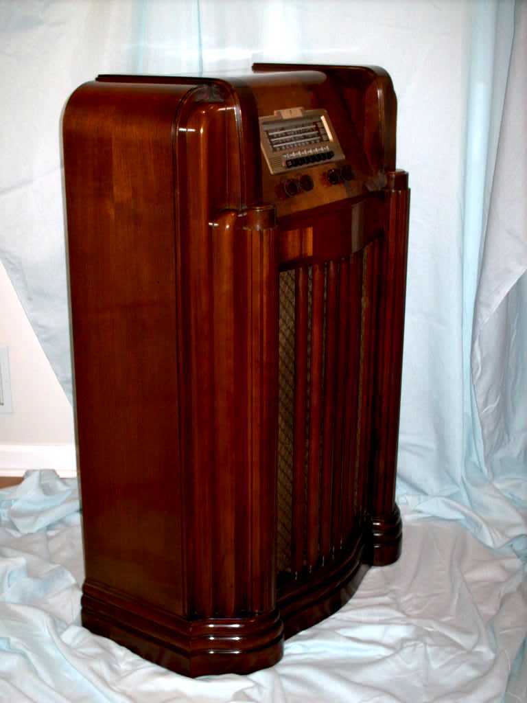
Shop pictures After
I will add some pictures of the finished radio with a repainted bezel (A muted GM Gold spray paint from the auto parts store looks great) and new push buttons from "Old Time Replications is owned and operated by Larry Bordonaro". You can see the new wine colored push buttons on the 40-150 page.
Runway ShotsPlease enjoy these pictures since adding Wine transparent push buttons, a good dusting and added station presets tabs. Just imagine your favorite nostalgic music or a sports game broadcast. Click on the little picture below for a lager image. This is the original finish. No need to strip and refinish this radio. Warm look beautiful sound. .
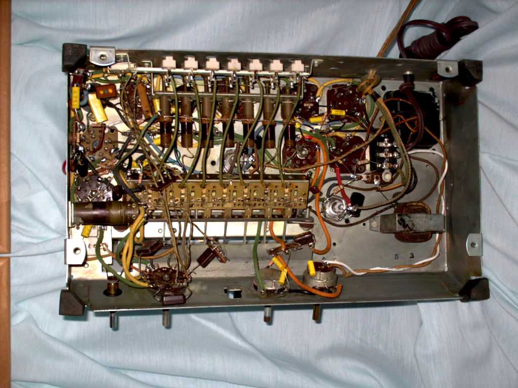
A second 40-190 chassis in for restoration.
A third 40-190 in for restoration.
The superintended.
| ||||||||||||||||||||||||||||||||||||||||||||||||||||||||||||||||||||||||||||||||||
Contact me including your thoughts and comments. 135,912 unique web site visitors (14,499,000 hits) from October 2004 through August 2011. Copyright © 2004 - 2012. All rights reserved.
|