|
This page describes how to test an Electrodynamic speaker. The Electrodynamic
speaker has a field coil to generate a constant magnetic field that the voice
coil opposes. These are basic Go No-go tests and not the extensive
frequency and impedance response tests. For extensive speaker tests find a
Speaker Cabinet building book. Radio Shack and Sam's (of the Sam's
Photofact line) sold good beginner volumes. Two other books are pictured below.

These tests are typically done in the cabinet. But a proper self
respecting restorer will pull the speaker to clean the dust out.
First, clean-up and physical movement check.
 This
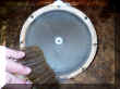
speaker is from a Philco 39-30. This
speaker is from a Philco 39-30. |
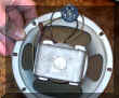
 The Voice coil gap is exposed. No dust cover.
 |
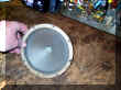
 Knock off the dust being careful of the dry brittle delicate paper cone.
 |
. Carefully clean the dust from around the voce coil gap. Use low
pressure air or gently blow out the dust from the gap.
Carefully clean the dust from around the voce coil gap. Use low
pressure air or gently blow out the dust from the gap. |
 Clean the dust from the back side.
 |
 Clean.
No debris to buzz and rattle Clean.
No debris to buzz and rattle |
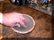 Gently
move the cone in and out. Listen for any scratching. Gently
move the cone in and out. Listen for any scratching. |
I have used rubber cement and Tea bag paper to patch
tears. The added mass will lower the resonant frequency of the
speaker. But you will not notice. Google speaker repairs for
more ideas. |
Figure out where the wires go.
The Field coil is independent of the other two coils and has two dedicated
contacts on this particular speaker. The Voice Coil is in series with the
Hum Bucker Coil. The red wire connects the Voice Coil and the Hum Bucker.
This pair will be tested together with an ohm meter.
 This
speaker has three coils: This
speaker has three coils:
- Field Coil
- Voice Coil
- Hum bucker coil
|
The red wire that goes from the coil to the
contact on the speaker's metal frame comes from the Hum Bucker
Coil.
|
|
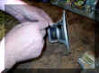
 The
arrow points to the Voice Coil. The Hum Bucker is below in
series. Colors are indicative of the cable coming out of the chassis
to the speaker connector and not the colors of the wires used on the
speaker its self. The
arrow points to the Voice Coil. The Hum Bucker is below in
series. Colors are indicative of the cable coming out of the chassis
to the speaker connector and not the colors of the wires used on the
speaker its self.
To
se the whole schematic click here. |
 The
field coil #44, is connected in series with the B+ high
voltage circuit. The current flow through the coil to the rest of
the circuit creates the magnetic field the voice coil's varying field
opposes. The hum bucker cancels out any induced 60/120hz ripple
hum. The
field coil #44, is connected in series with the B+ high
voltage circuit. The current flow through the coil to the rest of
the circuit creates the magnetic field the voice coil's varying field
opposes. The hum bucker cancels out any induced 60/120hz ripple
hum.
To
se the whole schematic click here. |
 This clip is from a Philco 38-4. It has the DC resistance of the
field coil marked on the schematic. The colors are for the wire
going from the chassis to the speaker jack.
This clip is from a Philco 38-4. It has the DC resistance of the
field coil marked on the schematic. The colors are for the wire
going from the chassis to the speaker jack. |
Test the Voice Coil and Hum Bucker Coil with a digital meter.
If the Voice Coil/Hum bucker combination is open:
- Check the individual coil separately.
- If the voice coil is open try re-soldering all connections. If that
does not work and the voice coil is open then the speaker needs
re-coned.
- If the Hum Bucker is open try to pull off some of the tap/insulation and
look for a bad wire near the surface.
Voice and Hum Bucker with an analog meter (VOM).
 Put
the meter on the times one (X1) scale. Put
the meter on the times one (X1) scale. |
 Short
the leads. See this meter does NOT read zero (0) ohms. Short
the leads. See this meter does NOT read zero (0) ohms. |
 Correct
this with the zero control. If the needle does not reach 0 then
the battery is weak. Correct
this with the zero control. If the needle does not reach 0 then
the battery is weak. |
 About 4.5 ohms. Good!
 |
Field Coil test with a digital meter.

Red wires - Field Coil |
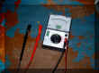
 This
Field Coil is bad. It should read about 700 to 2000
ohms. Most of the time the DC resistance is marked on the schematic
above. This
Field Coil is bad. It should read about 700 to 2000
ohms. Most of the time the DC resistance is marked on the schematic
above.
+/- %20 tolerance is good. |
|
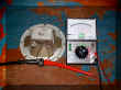
This is my test bench Electrodynamic. It has a
good field coil reading 1,145 ohms (1.14 k ohm).
|
If the Field coil is open or shorted:
- Try re-soldering all connections (open).
- Pull off some of the tap/insulation and look for a bad or a burned wire
near the surface.
- If that does not work and the field coil frame is welded toss it in the
garbage. There is not much you can do to fix it.
A bad Electrodynamic can be replaced with a permanent magnet speaker and the equivalent
wire wound 10 watt high power resistor in place of the field coil. Use
Ohm's Law formulas to determine exact wattage and add at least 20%.
Place it where the heat will not damage anything.
One caveat: If you plan to use a PM speaker put larger
capacitors in the circuit. For example, capacitor # 43 in the
above schematic clip, is 5uf should be replaced with a 10 or 12 uf (the next
standard value above 5uf). You will probably will replace them with larger
values any how.
Field Coil test with an Analog meter (VOM)
Lastly, check for shorts to the metal frame.
 Establish a good connection to the metal frame. Read zero ohms (some
meters read the lead resistance at less than one ohm).
Establish a good connection to the metal frame. Read zero ohms (some
meters read the lead resistance at less than one ohm). |
 Test
each point to the frame. Should read infinity ohms. Test
each point to the frame. Should read infinity ohms. |
 Click the Philco Repair
Bench web site to see typical speaker specs.
Click the Philco Repair
Bench web site to see typical speaker specs.
|
|
 |
[ Home ]
| 


