![]()
![]()
![]()
![]()
![]()
![]()
![]()
![]()
![]()
![]()
![]()
![]()
![]()
![]()
![]()
![]()
![]()
![]()
![]()
![]()
![]()
![]()
![]()
![]()
![]()
![]()
![]()
![]()
![]()
![]()
![]()
![]()
![]()
![]()
![]()
![]()
![]()
![]()
![]()
![]()
![]()
![]()
![]()
![]()
![]()
![]()
![]()
![]()
![]()
![]()
![]()
![]()
![]()
![]()
![]()
![]()
![]()
![]()
![]()
![]()
![]()
![]()
![]()
![]()
![]()
![]()
![]()
![]()
![]()
![]()
![]()
![]()
![]()
![]()
![]()
![]()
![]()
![]()
![]()
![]()
![]()
|
|
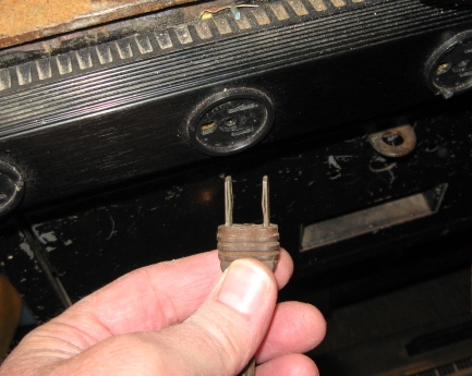
Back in my collage days (Disco was king) I worked full and part time as a field service man (Yes women were also Field Service Men too) repairing major medical equipment. The equipment included Electro Surgical generators (Bovie), Infant Incubators, Anesthesia machines (gas mixing resuscitators), EKGs and defibrillators. I took this job very seriously. Peoples lives were indirectly in my hands. Precision, accuracy and NBS (National Bureau of Standards) now called NIST tractability were the mottos of my job.One of the parameters that needed to meet safety criteria was eletrical safety. In other words, would the gear slowly or violently electrocute a patent to their final reward. Every repair manual (two were included with every device sold) included electrical safety checks and leakage parameters. The exact allowable leakage current specification alludes me now. But it was in the low micro amps (ua) range. I have taken these safety check practices to my own bench.Have you ever wiped your finger across a metal chassis and it felt like it vibrated across the metal? That is electrical current leaking from the wall outlet through the chassis into you. Remove the plug and the vibration feeling of the leakage will go away. Every thing plugged into a wall outlet will leak by virtue of capacitive or inductive coupling. Everything!Below are some pictures of my set up to test chassis leakage.
Now for some calculations.
NOTE: None of these leakage test apply to what is known as "Hot Chassis Radios", AA5's, radios with out power transformers. One side of the line cord is usually connected directly to the metal chassis, through a capacitor or through the whole radio circuit. And here is the kick in the teeth. The radio is HOT either with the power on OR with the power off depending on how you plugged the cord into the wall outlet! For me installing a polarized cord is self defeating. Trace a typical AA5 schematic. You will see what I mean.To my knowledge this electrical architecture is not manufactured any more. This was a cost savings strategy of the past.What now?Once you determine there is no danger you can leave all well enough alone. I choose not to re-engineer or modify radio chassis. I restore them to original.If you own the device you can install a polarize power cord with the wires connected to render the lower of the two leakage currents. You must also determine which line (wire) the power switch is in series with. Modern code want the HOT side switched and not the Neutral (wide plug blade).Or you could install a three wire grounded line cord. Now the chassis is connected to ground and should be safer. You should still put the lower leakage configuration across the two power wires with the power switch in the proper HOT line. This is a common practice among the collector/restorer. (This does NOT apply to Hot Chassis Radios!)It can get a little complicated when you try to MODIFY or reengineer a device to meet modern codes. But improvements effectively accomplished should help add safety to a device. I have to say that I do not recommend modifying anything unless you are "qualified".If you have to replace a power transformer in a radio chassis the new transformer rarely comes marked. That is marked as to what primary wire is to be connected to the hot side of the line cord, fused and switched. You may perform the above leakage test to determine which primary lead renders the least amount of leakage to the transformer core.Transformers are very similar to rotating motors. Many of the formulas used to analyze a transformer apply to a rotating motors. You may also use the above methods to determine the leakage of a motor (Your 1930's Mix Master) and what wire you would want connected through a switch to the HOT side of a wall outlet. (If the hot side is too complicated consider it from the Neutral side.)Happy testing. Happy Thanksgiving 2011.
|
Contact me including your thoughts and comments. 135,912 unique web site visitors (14,499,000 hits) from October 2004 through August 2011. Copyright © 2004 - 2012. All rights reserved.
|