|
Restoration of an Yaesu FT-101E.
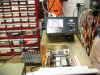
Below is the electrolytic order
sheet. The quantities are doubled so I can build my inventory.
 |
Verify quantities against your
parts list. I ordered double quantities.
|
|
You will see the note "FT101E for 16v
SUB". This is where a cap was not available in the lower voltage. Or
I just wanted to minimize bins.
|
|
All these caps are selected with 105
deg Celsius. The original caps are 95 deg C.
|
| All caps are Radial. The
leads were long enough to stretch for axial replacements. Use a bit of
Heat Shrink Tubing or spaghetti.
|
| Add C13 80pf 1kv and C131
1000pf 1kv (the factory installed capacitor is 500volts) to your order. One is a coupling cap from the driver
tube to the PA tubes and the other looks to be feedback. Degradation causes
high tube bias and excessive heat. This was advised by a FoxTango
contributor. These are below the electrolytic cap list.
|
| Add R37 18k 5w and R5
5.1k 5w resistors. I found R37 cooked. It had been arcing to the
chassis from an exposed section of the resistor body (missing insulation).
The cap above it was cooked too. It is a suggested mod of a 50 uf at
450 v. I did not replace it. These resistors cook it.
|
|
|
| The biggest challenge is to
find complete alignment information. Some information is found on the
board detail pages for each board. And most of the alignment
adjustments are inferred. One must use experience and good judgment to
determine the best setting of individual pots, trimmer caps and tuning
slugs. I have documented all of my setting with in my copy of the
service manual.
|
 It
is best to use an external power meter when tuning up the
101. It
is best to use an external power meter when tuning up the
101. |
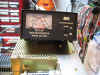 Keep
an eye on the plate current. Keep
an eye on the plate current. |
 What
is this trimmer cap for? What
is this trimmer cap for? |
|
|
| |
|
|
|
|
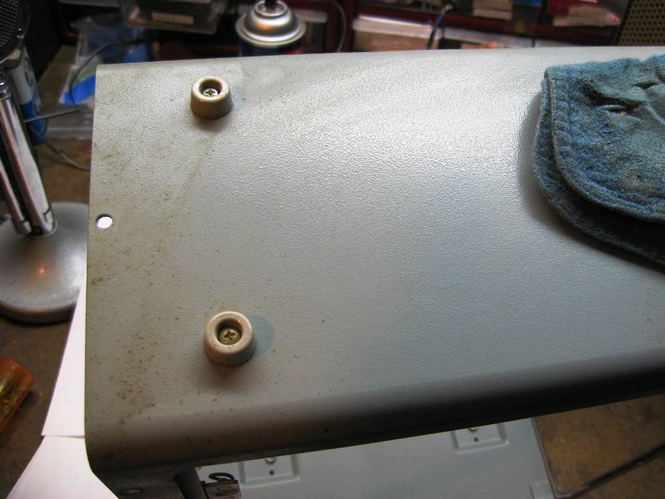
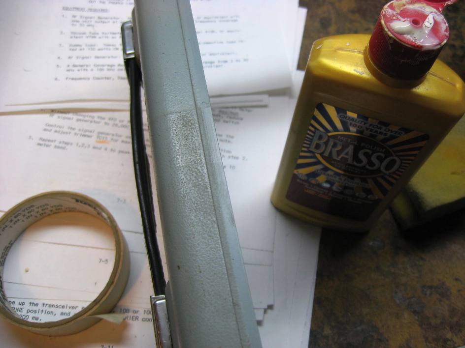
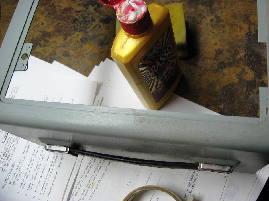
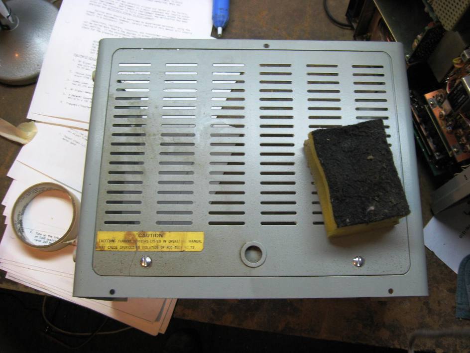
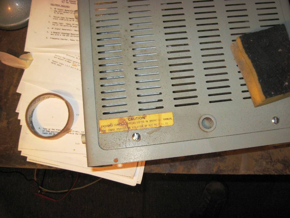
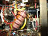
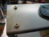 Cleaning
the cabinet with Brasso. Cleaning
the cabinet with Brasso. |
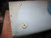 |
 The
grit in Brasso helps remove dirt and corrosion. The
grit in Brasso helps remove dirt and corrosion. |
 |
 |
 |
|
|
|
|
And now for some of the challenges
that I encountered.
Finding a matching
schematic.
I had found discrepancies with the
schematic that I was using for the 101E and this unit. There is a coil and
two capacitors in the shape of a tank circuit from the lamp to the relay.
Then a wire from the relay to the Receiver RCA jack. The schematic shows
no such components.
Peter of Surry UK G4DJB
offers:
"Schematics - do not believe
them 100%. I have also found differences between my 101E and the schematics,
plus you will find that there are a number of different versions of schematic
just for the 101E alone. Unfortunately, Yaesu did not mark them any differently
(they could have put a version number or date on them) so there's no way of
telling which schematic you have. It sounds as if you have a late model 101E and
the schematic for an earlier 101E. I'll see if I can find a copy of the late
101E schematic for you. I do have one that shows the components between the lamp
and relay as you describe, but its part of a very large pdf file - far too large
to email or upload to the files section."
And he did send me a schematic that
matched the unit. Thanks again Peter!
Heterodyne Output adjustment (p 7-8)
Note - With
a rig of this vintage I would perform the Power supply voltage adjustments p
7-11 then Heterodyne Alignment as my first two alignment steps. I went
through the whole preselector balancing procedure only to find the Heterodyne
oscillator signals were in need of alignment. This may or may not affect
the rest of the alignment. But is dose seem to be a logical thing to do.
I was trying to set the initial
oscillator amplitude of 0.3 v rms with the
trim pot and the T111 but could not get the amplitude. I used a scope looking for 0.8484 volts p-p. Page 7-8 of the service manual.
Also the trim pots do not line up with the FT-101E band dial. This unit
10D band is adjusted with TC-23 and not TC-24
The second paragraph on page 7-8 does not address all of the crystal trim pots (6 out of 11 trimmers). Is there a reason for this omission? I set
them all for .3 rms (.8484p-p).
R22 on PB-1181 should be 56 ohms oscillator buffer transistor emitter resistor. It was 22 ohms. This held the TP signal below the .3 v
rms. Once I changed this to the schematic value I could properly set the oscillator levels. It looked to be factor, w/ properly bent lead so it
would push too far through the PC hole and beige color coated (not the value bands). Boy I fought this for hours changing both oscillator transistors
before I started measuring discrete resistors and found it (first resistor I measured by the way).
I had removed a couple of resistors that were oldered across the trim caps
used for the level control. Once R22 was the correct value these bands
could not be set low enough and had distorted sine waves. So I put those
undocumented mods back. 160 meters took an 820 ohm parallel resistor to
the
trim cap, 40m took a 1000.
This rig was set up for C.B. I have been removing the changes and
restoring this unit to original configuration.
I was informed by Peter of Surry G4DJB, UK a FoxTango
Yahoo group participant, "R22 on the PB-1181 was changed in value (by
Yaesu) in the last production batch of FT-101E radios from 56-ohms to 22-ohms.
It seems as if your radio prefers the old values!"
With a rig if this vintage and age I
would perform the Power supply voltage adjustments p 7-11 then Heterodyne
Alignment. I went through the whole preselector balancing procedure only
to find the Heterodyne oscillator signals are whacked out.
I used a O-scope to set the levels
and some of the crystals did not present a sinusoidal wave shape.
"This is normal." Peter of Canada VK4JD said, "I noticed
this when tuning up a 101Z recently. The TX output was clean on the
spectrum analyzer and I didn't detect and RX spurious related to oscillator
multiples." A spectrum analyser is good enough for me. I also
check for the harmonics on a communications receiver.
NTE-454 Front End FET upgrade (Q1
PB-1181 3SK40M)
I tried the NTE 454 FET recommended
on the FoxTango site. I heard very
little improvement over the stock FET. I ordered two. The first
NTE454
degraded the reception. It curiously came re-heat sealed from Mouser.
The second was in original blister packaging. Both had anti-static warnings.
The second NTE454 had a barely perceptible improvement with .3 uv input or there about. I suspect people that have heard a noticeable improvement may
have had compromised (damaged) original FETs.
Now please realize, if you need a
new Q1 FET this would be a fine substitute.
VR-1 on PB-1181,
there is a note tucked away in the corner on Page 5-11 of the Service Manual
that says that "VR-1 is set for minimum signal level at 3840 kHz when
transmitting on 3800 kHz as heard in a separate receiver". From Peter
G4DJB.
S-meter adjustment and. NB
Adjustment.
Page 7-9 (VR-2 PB 1183, Q5
emitter) I was not able to get
the S-meter to 20 over 9 with 50 uv at 14,200. When I wiggle the lamp in
the socket the signal jumps a bit. When I short the lamp socket with a screw
drive the signal pick up 2 S units. But it never reaches the 20 over 9
reading.
The solution is two fold.
Clean the fuse/lamp socket and lamp base and re-solder the lamp socket
leads. This stabilized the receive signal when the lamp was tapped.
The low S-meter reading generated
discussion on the FoxTango
Yahoo group, relative to the accuracy of S-meters in general (and some
specific). The bottom line for me is the calibration did not meet the
criteria set by Yaesu. And that is an indication of trouble.
The solution is to align the IF sections of the circuits before this
board See Noise Blanker below.
Noise Blanker PB-1583 (the FT-101e
version)
The break through that restored the
S-meter sensitivity and the whole receiver's sensitivity, came when adjusting
TC1 and T120 on PB-1583 p 5-35.
Starting at the IF input (3180k)
with the internal marker Generator on, set to produce a 100hz tone, use the
S-meter for peak indication. "Rocked" the transformer T120 while
peaking TC1 (just like the 600khz alignment on an AA5) and WOW!. The
S-meter reading kept climbing and climbing. Off the scale....pegged!
Reduced the RF gain to keep the meter on the scale and kept rocking and peaking.
What a difference! I put a random long wire on it (the one thrown up into
the trees) and started pulling in stations from all over on 20m! I am tickled
pink. I now could then back down the S-meter setting (VR-2 PB 1183) and
set it to 20 over 9 with 50uv at 14.200 as in the cal procedure.
I continued on with the 455k
transformer, T123. A receive signal is needed for proper adjustment of
T123. Again set the internal marker generator to output a 1000 Hz tone, NB
switched on, O-scope on the TP and dip the DC for minimum. You need to receive
a signal to generate AVG.
I tested the NB by taking a Weller
soldering gun, wrapping the long wire antenna around it and alternating the
trigger switch from high to low power. The NB works as indicated by the
S-meter staying steady with the NB on.
Cold Neutralization of the FT-101,
by Peter Roberts G4DJB
|
The standard neutralization method used by FT-101 owners suffers from a
couple of major drawbacks - the finals are producing RF (i.e. are `hot')
and the method requires a lot of tweak and try. This results in a
lengthy process during which the finals may get very hot, or may even be
destroyed if they should go into oscillation and the operator is not
quick on the OFF switch. The method described here is not new, but may
be new to some FT-101 owners. It allows neutralization of the finals
whilst they are `cold' (not actively producing RF). The operator may
therefore take their time and there is no chance of the finals being
damaged.
As pointed out, this method is not new. Please refer to an excellent
website by Tom, W8JI (www.w8ji.com/neutralizing__amplifier.htm)
in which he discusses the need for neutralization and ways it may be
achieved. The cold neutralization method works as it takes advantage of
the fact that inter-electrode capacitances are present whether the
device is `hot' or `cold'.
In a `cold' device, the grid-plate capacitance acts as a path through
the circuit, and so a proportion of the drive signal will appear at the
output. The purpose of neutralization is to couple an amount of signal
back to the driver equal in amplitude and in antiphase to the finals'
grid-plate coupled signal. So, the net effect should be to cancel out
any signal feed through. In practice, cancellation will not be complete,
but it is possible to adjust for minimum feed through.
In the FT-101, `cold neutralization' is achieved as follows:
1. Make sure that the transceiver has the PA compartment covers fitted
(top and bottom).
2. Switch on the radio. Tune the radio as normal for maximum transmitter
output (into a 50-ohm dummy load) at 29.0 MHz. Switch off the radio.
(You can miss this whole step if you are worried about the finals
oscillating)
3. Remove the "Accessory" plug from the rear panel. This opens
the heaters in the finals, but keeps the heater active in the driver.
4. Connect the transceiver RF output (ANT connector) to a detector of
some sort. (I use an oscilloscope with a BNC "T" piece
adaptor, the third arm of which has a 50-ohm termination directly
mounted to it. A standard communications receiver will probably be too
sensitive, may suffer damage, and may not give accurate results).
5. Switch on the transceiver, and switch on the Heaters. Make sure that
the finals are not lit, but that the driver is!
6. Set frequency to 29.0 MHz and set the mode switch to TUNE.
7. Set the carrier level control to about 3 and set the MOX/PTT/VOX
switch to MOX.
8. Adjust the Preselector, Plate and Load controls for MAXIMUM signal on
the detector (scope). Adjust the carrier level as needed to get a
suitable level.
9. Adjust the neutralization capacitor TC27 (using a non-metallic
trimming tool) for MINIMUM signal on the detector.
10. Re-peak the Plate and Load controls for MAXIMUM and re-adjust TC27
for MINIMUM. Repeat until no further reduction in signal at the detector
can be achieved.
11. Set the MOX/PTT/VOX switch to PTT, the heater switch to off and the
radio power switch to off. Remove the detector from the ANT connector
and re-fit the Accessory plug.
You should now find that maximum RF output coincides with the dip in Ic,
or is very close to it.
Detector Notes.
The choice of `detector' is entirely up to you. There may be up to
1-Watt RF present during this process, so you will need to act
accordingly. As stated above, a communications received is probably not
a good idea. I found that a lot of attenuation was required between the
FT-101 ANT connector and the radios' antenna terminal and that RF was
leaking around the attenuators making accurate adjustment impossible. As
an alternative to an oscilloscope, a simple detector (perhaps following
a 50-ohm attenuator) using a diode and multimeter should be adequate.
For making adjustments, an analogue meter is preferable to a digital
one.
|
I have some more procedures
developed. I will be adding these at a later date.
In conclusion
Peter of Surry UK G4DJB puts it,
I must extend thanks to all the
contributor on the FoxTango
Yahoo group. As the Beatles sang, "With a little help from my friends."

PARTS as
of 2009
This is the list of parts that I
replaced for this restoration. You should be able to click on the Mouser # then add a quantity to your
cart. I hope this saves you some time.
Part
Numbers
Customer Label Suggested QTY
This is a second order for C13 the coupling capacitor from the 12BX7 to the
final output tubes. Q1 is a FET that exceeds the performance and has diode
input surge protection. It is alleged to significantly improve the
sensitivity of the 101 (I believe it but have not tried it yet).
Location.
|
Mouser part number and description.
|
|
Qty per chassis
|
C13 coupling capacitor, main chassis
|
598-CDV19EF820JO3F
82pF 1000V +/-0.05%
|
FT101E
|
1
|
Q1 of the RF board.
|
526-NTE454
TO-72 DUAL GT MOSFET
http://www.foxtango.org/ft101/foxtangoft101module.htm
|
06/09/09
|
1
|
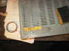
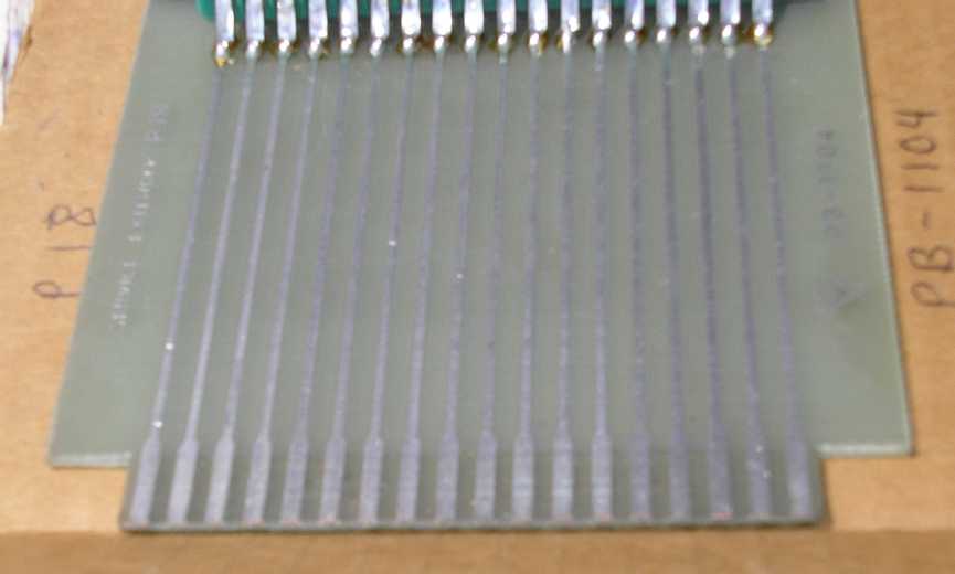
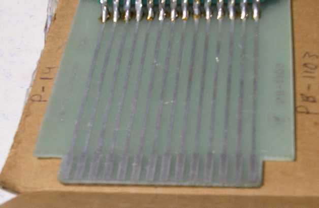
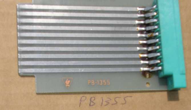
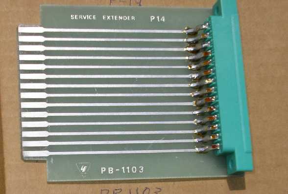
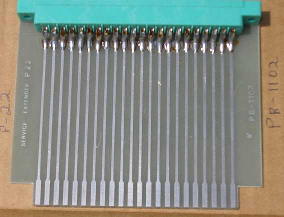
Extender Cards
These are pictures of original
Yaesu Extender cards kindly supplies by Kendwell AB1JZ. I have been
looking into making these boards. The boards will not be anything special
but will get the job done at minimal cost for a set.
 This
is an 18 pin extender that I cobbled together from an old relay board and a
surplus card edge connector. It helped me troubleshoot the PB-1811 RF
board. It may not be pretty but it works. This
is an 18 pin extender that I cobbled together from an old relay board and a
surplus card edge connector. It helped me troubleshoot the PB-1811 RF
board. It may not be pretty but it works.
Here are some numbers
for edge connectors. A 15 pin connector can be used for the 14 pin
boards. Just shift the board over to one side. Put an insert or key
in the 15th position of the female connector.
| Product Detail |
Order Qty.
|
Price
(USD)
|
Ext.
(USD) as of 2009
|
|
|
|
$4.52 |
$4.52 |
|
|
|
$3.72 |
$3.72 |
|
|
|
$4.66 |
$4.66 |
|
|
|
$2.44 |
$2.44 |
| For
additional information on availability, click on the Mouser Part #. |
MERCHANDISE TOTAL:
|
$15.34
(USD)
|
|
Here are the files I created with a particular PCB board
manufacturer's free software. I found this manufacturer in Nuts and Volts magazine. I have done no business with them so
you are on your own.
The free software
from www.expresspcb.com is needed to
open the files
below. My copy of MS Explorer is changing the extension to
"html". If this happens to you change the extension back to
"pcb". I am not sure why this happens with MS and not with Google
Chrome. Go figure.....
| Theses images were "printed" from the
below files. (Not to scale.) |
 Image "printed" from the below file..
 |
 |
 |
 |
| These files are the working ExpressPCB
application files or source files. |
10 pin card
work file. |
14
pin card with 15 pin connector. |
18
pin card |
22 pin card |
These are my rough calculations:
Cost to make a set (4) of Extender cards using;
Express PCB and Mouser (2009)
|
|
| |
| |
| |
|
|
|
|
|
|
| SETS
of 4 |
4 |
20 |
25 |
50 |
100 |
|
| card
edge connectors |
$72.00 |
$310.00 |
$334.00 |
$621.00 |
$1,161.00 |
Mouser |
| 10
pin PC |
$91.09 |
$131.00 |
$156.00 |
$238.00 |
$397.00 |
ExpressPCB |
| 14
pin pc |
$93.55 |
$212.00 |
$255.00 |
$430.00 |
$792.00 |
ExpressPCB |
| 18
pin pc |
$99.83 |
$244.00 |
$296.00 |
$511.00 |
$952.00 |
ExpressPCB |
| 22
pin pc |
$105.95 |
$270.00 |
$333.00 |
$577.00 |
$1,086.00 |
ExpressPCB |
| |
|
|
|
|
|
|
| Initial
investment |
$462.42 |
$1,167.00 |
$1,374.00 |
$2,377.00 |
$4,388.00 |
|
| |
|
|
|
|
|
|
| Cost
per set of 4 cards |
$115.61 |
$58.35 |
$54.96 |
$47.54 |
$43.88 |
|
I ordered a set of Extender boards
from BAS. They
arrived from Holland with in a week or 10 days! I am impressed. He
gave me a great price compared with my research above, and all other offers I
heard to date. I will pick up a set of card edge connectors from Mouser
with my next parts order.
There
was a bit of confusion. BAS sells complete extender boards with
connectors. Please contact him directly, via email below, for costs. I
asked BAS what I should post for him. Below is his September 23, 2009
answer.
Thanks Paul,
Complete set is $125 as I emailed you before. I got a bunch of emails
from various countries to ask for bare boards but I've also seen the
Ebay listings of extender boards and I don't want people to sell my
boards for a lot of money. They are tools and have to be used to repair
and restore various rigs for the amateur. It is still hobby for me as
well!
73!
Bas.
|
BAS
said, "The
boards are made with Eagle and are exact on the .156" grid."
I have an other 101
restoration/Elmer at the Skyview Radio Club coming up. A member has one to get
back on the air! These are not collector or original Yaesu board but will do quit fine for my application.
I scanned these
boards.

Click to
enlarge, they look better bigger. |
 |
The 10 pin is double sided. The other three have traces
on one side only.
BAS's contact
information is: Temporarily removed.
Good luck and happy boarding! Surf's
up baby!

Helpful Links

|


 This
is an 18 pin extender that I cobbled together from an old relay board and a
surplus card edge connector. It helped me troubleshoot the PB-1811 RF
board. It may not be pretty but it works.
This
is an 18 pin extender that I cobbled together from an old relay board and a
surplus card edge connector. It helped me troubleshoot the PB-1811 RF
board. It may not be pretty but it works.