Motorola 50-X-1 Pre 1941 Art Deco style table radio.

The Motorola 50-X-1 manufactured by the Galvin Manufacturing Company is
listed as a Broadcast Band (AM), pre 1941 radio by NostalgiaAir.org
(see Links page), Riders volume 12 pp 26, 35-36. It is a five tube AA5
(All American Five) radio with the following Tube Line-up:12SA7, 12SK7,
12SQ7,50L6 and 35Z5. It has an Electro Dynamic (no permanent magnet)
speaker.
The case is made of Bakelite with an Art Dec styling to the speaker grill,
dial face and knobs. This particular case is in great condition with no
cracks. It has only a scratch on one side that darkened with
treatment. Once cleaned and conditioned the rich dark brown of the
Bakelite shows its vintage with a very slight marbling/swirl effect. The
dial lamp (new) illuminates the dial scale and casts a soothing glow onto the
table in front of the radio.
Circuit restoration was quite straight forward. Most of the resistors
(all were replaced) were way out of tolerance and all wax/paper and electrolytic
capacitors were replaced. The unit required three UL rated safety
capacitors (15, 17 &18). Two in the circuit and one for the external
antenna lead. Capacitor 17 from the circuit common to chassis ground keeps
the unit from self oscillation and receiving birdies at the band end. The
two section electrolytic filter capacitor was replaced by discrete capacitors on
an additional terminal strip. The terminal strip, being solder mounted to
the chassis, provided a convenient place to attach C-17 from ground to chassis.
One of the five tubes 50L5 tested bad with a short circuit with in and was
replaced.
Once restored and aligned the radio is sensitive and plays well across the
whole broadcast band. Band coverage is from 1720 to 530 K cycles.

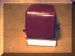
Front side of restored radio. The cabinet was cleaned with Clorox
Clean up and treated with Magnolia Glayzit. This radio was covered
in cigarette tar and smoke, which is typical of radios this vintage. |
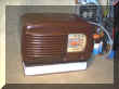
The dial scale cover was also treated with Glayzit. It was not necessary
to put this cabinet in the dishwasher. |
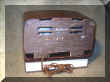
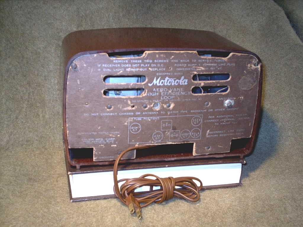
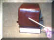
The rear is marked with the Galvin Manufacturing Company. The
antenna trimmer capacitor and external antenna screw are also
visible. This is a great set up for a long wire antenna to pull in
the distant stations that may otherwise not be received. |
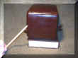
You can gauge to compact size of this radio from the pew bible that
is underneath the unit. |
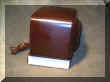
Side with a scratch. |
This picture has been enhance to show the extent of the
scratch. It is not this noticeable when viewed directly. |
This is a more realistic view of how the scratch looks. |

Underside with the chassis retaining screws. It is best not to
set this radio on a metal surface. |
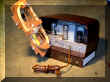
Inside View. The antenna has fanstock clips to attach the wires
from the chassis. You don't see this often. |
To properly restore, clean, polish, treat, align and test this radio it took approximately
five (5) hours of labor. It was "burned -in" for 24 hours (one
hour prior to alignment). Every component was verified against the
schematic for proper value and circuit connection. There were some wrong
value components installed during a previous servicing (this is unfortunately
typical of radios of old vintage) and a shorted audio tube.

|