|
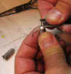
In the picture you can see the little hook looking part of the safety
pin. That is to be epoxied into the knife handle.
|

|
Insert the cut pin with the loop into the knife blade holder.
Press the epoxy into the gap on the hook side of the pin. Leave the
other side free of epoxy. Or push the epoxy into all spaces in the
gap and clear one side out to receive the unbent end of the new component
(to be twisted).
|

|
Tighten the handle real tight! I over did it a bit and warped
the handle. But this will keep the little wire (from the safety pin)
tight.
|

|
The new part lead goes into the side where you scraped out the glue.
It has to go in about 1/8 to 3/16 inch or more.
|

|
Shown it an old part clipped out of the circuit. The lead wires
have been clipped at the capacitor's body. Get an "eye
ball" idea of where the new coil loop are to end. Or how far
should you twist up the new lead wire.
|

|
Push the new lead wire into the tool.
|

|
Pull the part down at a right angle to the "winding pin"
(the former safety pin).
|

|
Twist the wire a few times to form a spring or a few loops to slip
over the old parts remaining lead wires.
|

|
Try to keep the loops the same distance apart as the body of the old
part.
You can shorten up (wind more coils) if the old lead wires closer
together. You do not want to do this in position sensitive chassis
like a Zenith Transoceanic RF/IF sections.
|

|
Trim the lead wires to make it neat looking.
|

|
This is the capacitor shown above installed in a chassis. It is
a cathode bypass capacitor in parallel with a cathode resistor in this
Saba Freiburg 14 Vollautomatic.
|
The alternative to twisted leads are
little hooks.
Cut the the leads of the old part at
the body of the part. Form two little hooks on the old leads. Form
opposing hooks on the new part. Engage the hooks, crimp them closed and
solder.
"Well",
you say, "Paul, why don't you unsolder the part at the solder tab of the
tube socket? Besides it is the right way and better looking to totally
replace the part!" I used to do that until I broke a few tube sockets
and brittle terminal strips. It is very frustrating to acquire and replace
a matching tube socket in a vintage radio. I replaced a few in Zenith
Transoceanic cramped chassis radios. This "snip and replace"
technique keeps the new part centered, in the position where the factory placed
it (as in the aforementioned Transoceanic). You never know when a
components position is critical or not. You do not want to go through al
the work of replacing parts and come to find you induce hum in an amp, created
cross-talk/feedback or detuned a critical RF, IF or oscillator circuit.
And, I don't mind saying, this way (or the hook method) is much, much
quicker.
I use this technique
on PC board too. Try and not lifting a copper trace off of the PC card
while removing an original part, causing damage. It is hard for me not
to. So I clip out the part, stand the led wire perpendicular to the PC
board, slip the twisted lead wire over the old leads and solder. I have
not lifted a trace yet using this method.
This Lead Twister may be the
primary tool that I use for all restorations.

