PYE P35


Home Search Aetna Airline Atwater Kent. Bendix Blaupunkt Bogen Bowers Breting 14 Bulova Crosley Delco Dentron Electro-Neutronics Emerson Emud Fairbanks Morse Grant, W. T. Grebe Grundig Grunow Hammarlund Hallicrafters Heathkit Henry Hickok 288X Howard Howard Johnson Jesse French Johnson Korting Lafayette Lap Amp Motorola NAD National. Nordmende Norelco Packard-Bell Perpetuum-Ebner PHILCO Philips PYE P35 RCA Robyn T-123B SABA Silvertone 4663 Standard A Stewart Warner Telefunken Triplet 3436 vhf gen Wagner Walgreen WEGA Westinghouse Yaesu ZENITH Links Audio Reinforcement Antenna Cabinet Finishing Capacitor stuffing Comments Dial Scales Dim Bulb Tester Electrodynamic Electrostatic Elmer is his name. Etching Emblems IF Transformers Lead Twister Leakage Tester Packing Tips Resistors Rodent Damage Shiny Chassis Slides & Presentations Tube Analyzing Vendors Laptop


wpe15.gif (74715 bytes)  Click to enlarge the specifications.


This is a PYE P35 manufactured for England and the European continent.  It runs on 210 to 250 VAC and needs a step up transformer here in the states.  After restoration this radio is rather sensitive.  Bands start at 2000 meters (150 KHz) Long Wave (LW) and goes up through 18 MHz.  

Interestingly the Mid Wave (MW) band and the low end of the "Trawler" (as refered to in the alignment procedure) MSW band cover the US broadcast band.  The LW and MW band is labeled in meters so one must do a conversion from frequency to meters when locating a station.

Wavelength (or Lambda) in meters   =   300,000      /    f     (frequency in KHz.)

                                                                        300,000     /    1020 KHZ    (KDKA Pittsburgh) 

                                                                        294  meters on the MW dial scale


The challenge with this chassis was the broken oscillator coils.  Two were out of their metal retainers. I suspect the plastic has shrunken over time and shipping broke loose the fine hair like wires. The antenna coils were loose also.  So after some delicate soldering, with no coffee, the coils were repaired.

Pitch or tar was used to secure the aluminum and pressed iron powdered tuning slugs from detuning from vibration.  That was a point of focus.  A heat gun was used to soften the pitch and several alignment tools were employed from plastic, fiberglass to carved wood to perfect the alignment.

Once the radio was fully restored and aligned it received well on an external antenna.  There is no internal antenna so a long wire antenna is a MUST for strong Long wave Broadcast and Shortwave reception.  (If you live near broadcast stations then a few feet of antenna wire on the floor may be all you need.  But you will need some lenth of wire.)  A suitable ground may also be needed.  

Unfortunately, I do not know a source for the British pins that plug into the antenna, ground, speaker and PU receptacles.  I used snugly fitting (slightly zig zag bent) stubs of solid copper house wire.  I will be keeping my eyes open for a properly fitting pin jack.  I suppose one could have them fabricated from Hobby Shop brass tubing or rods.

The copper wire stubs worked well for the PU or Phono Pickup connection.  Keep in mind this is near a line level input looking for a crystal or ceramic phono pick-up.  I connected a CD player into the PU connections using an old headphone cable and alligator clips.  Connect both Left and Right to the upper PU connector.  The Shield goes to the lower connector (gnd). 

Service information can be found on line from http://www.radiomuseum.org/r/pye_p35p_3.html.


Click on a picture to enlarge.  
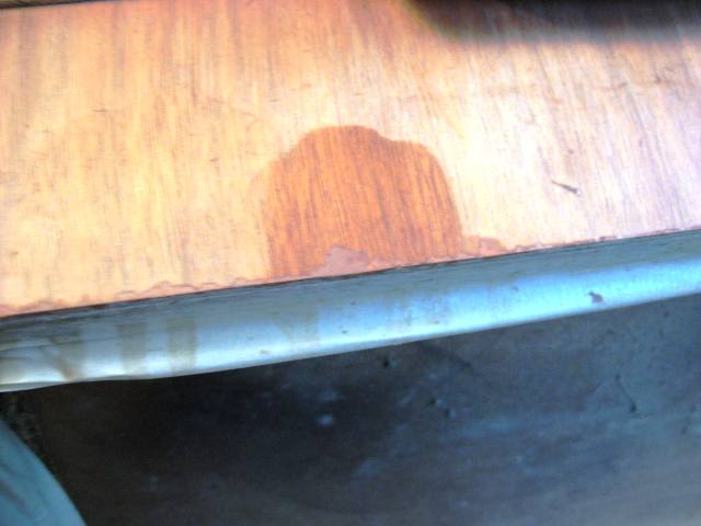
IMG_1541.JPG (80989 bytes) This inside.  Pretty clean. IMG_1542.JPG (113600 bytes) The broken oscillator coils. IMG_1547.JPG (61901 bytes) Dislodged antenna coils made with "Unobtainium".  IMG_1553.JPG (67841 bytes) A stub of wire was coaxed from around the retaining mount and a new lead wire was soldered. 
IMG_1562.JPG (57091 bytes) And the second coil which is a transformer.   Replacement coils are not made.  These are either repaired, rewound or salvaged from other donor units.   IMG_1549.JPG (17845 bytes) This is a new replacement capacitor of the same capacitance but double the working voltage.  What a difference advances in materials makes in electronics. IMG_1550.JPG (24329 bytes) The original 1/4 watt 20% resistor on top compared to the new 1/2 watt 5% resistor on the bottom.
IMG_1567.JPG (107956 bytes) Rear view. IMG_1570.JPG (366757 bytes) Front view. IMG_1573.JPG (124006 bytes) Dimmed room lights.  IMG_1566.JPG (133012 bytes) A scan of the dial glass with alignment points marked.  
IMG_1575.JPG (29085 bytes) This is the Homebrew Step-up 1.5kva  transformer.  Isolated primary and secondary.  This box is bigger than the PYE and is on it is own wheels. IMG_1576.JPG (57468 bytes) Heavy stuff. Properly switched and fused.  It was originally wired for 600 volts output to run a linear RF power amplifier. IMG_1579.JPG (278446 bytes) An imported  1000VA step-up  autotransformer. IMG_1574.JPG (268358 bytes)It runs the unit just fine with no line isolation.  It is not UL rated. but perfect for the shop.  This unit is much smaller than the PYE.
IMG_1627.JPG (252928 bytes) IMG_1622.JPG (124313 bytes)  IMG_1621.JPG (139306 bytes) IMG_1619.JPG (45786 bytes)  IMG_1618.JPG (42546 bytes)


This cabinet is to be refinished.

One challenge is to reproduce the logo decal on the top of the cabinet.  I could not find a vendor that supplies British logos.


IMG_1631.JPG (37476 bytes)Measure and photograph the original before stripping. IMG_1630.JPG (20993 bytes) IMG_1723.JPG (25344 bytes)Import picture into Visio IMG_1724.JPG (198657 bytes)Create an outline to be filled in using MS Paint. IMG_1725.JPG (136881 bytes)Re-import filled in image into Visio, set final size and duplicate.
IMG_1726.JPG (171981 bytes) Duplicate IMG_1727.JPG (153794 bytes)Make mask for gold painted background. IMG_1738.JPG (222395 bytes)Make many decals with laser jet decal paper.  The ink jet just did not want to work for me. about 10% of the images were good. IMG_1730.JPG (135584 bytes)Fill in gold background.  IMG_1731.JPG (169821 bytes)Looks bad.
IMG_1743.JPG (207965 bytes)Test different gold backgrounds on scrap finished wood. IMG_1744.JPG (197132 bytes)Background too big.  Make a smaller mask.  IMG_1747.JPG (253644 bytes)Final placement on the refinished radio cabinet.  Use Decal setting solution from the hobby shop.  IMG_1780.JPG (2172065 bytes)

I am sort of proud of this logo.  A lot of work went into reproducing this decal. It is a good thing computers and printers are available. 


Refinishing steps.

IMG_1635.JPG (38084 bytes)Take everything off of the cabinet and mask off openings.  IMG_1637.JPG (47765 bytes) First application of stripper.  IMG_1636.JPG (46197 bytes) IMG_1653.JPG (48190 bytes)Old finish stripped.  Original stain maintained. IMG_1654.JPG (44996 bytes)
IMG_1655.JPG (38769 bytes) IMG_1656.JPG (40609 bytes) IMG_1657.JPG (40772 bytes) IMG_1658.JPG (43338 bytes)The veneer is chipped. IMG_1659.JPG (184632 bytes) Press in wood filler. 
IMG_1660.JPG (44136 bytes) IMG_1664.JPG (45785 bytes)After shaping and sanding stain the filler to closely match the veneer. IMG_1665.JPG (40475 bytes) A little closer.  IMG_1666.JPG (43186 bytes)Deodorized mineral spirits temporally darkens veneer for a test.  IMG_1667.JPG (32543 bytes)Closer still.
IMG_1746.JPG (1754195 bytes)The cabinet has received approximately 6 to 8 coats of clear lacquer. IMG_1778.JPG (735997 bytes)  The filler has been touched up with grain lines and two shades of Mohawk Toning Lacquer to blend the wood filler into the veneer.    


Final pictures of the refinished and restored PYE


Before cabinet refinishing. IMG_1771.JPG (1822754 bytes)After 6 to 8 coats of lacquer, grill repainted to match the logo and some gold fill in the knob lettering.  IMG_1772.JPG (1394639 bytes) IMG_1773.JPG (1843928 bytes) IMG_1776.JPG (1308384 bytes) The grill received a good scrubbing and painted with the same gold paint as under the logo.
IMG_1774.JPG (1318242 bytes)  IMG_1778.JPG (735997 bytes)  There was not much left of the lettering depressions to fill with gold paint. But some filler remained.  IMG_1784.JPG (1984015 bytes)This was taken with the Florescent shop lights with flash.      


Hit Counter


 Contact me including your thoughts and comments. 

Please see the LINKS page.  I have collected many resources over the years.

135,912 unique web site visitors (14,499,000 hits) from October 2004 through August 2011.

Copyright © 2004 - 2012. All rights reserved.